Foot stand

A technology of tripods and positioning columns, applied in the field of tripods, can solve the problems of labor-consuming and time-consuming fixing methods, inconvenient users, changing the position and projection direction of projection devices, etc.

Inactive Publication Date: 2014-10-15
CORETRONIC
View PDF14 Cites 1 Cited by
  • Summary
  • Abstract
  • Description
  • Claims
  • Application Information

AI Technical Summary

Problems solved by technology

However, the fixing methods of the known fixing mechanisms are mostly labor-intensive and time-consuming, and it is difficult to change the position and projection direction of the projection device arbitrarily through the fixing mechanism, which causes inconvenience to users

Method used


Image

  • Foot stand
  • Foot stand
  • Foot stand

Examples


Embodiment Construction

[0068] The foregoing and other technical contents, features and effects of the present invention will be clearly presented in the following detailed descriptions of multiple embodiments with reference to the drawings. The directional terms mentioned in the following embodiments, such as up, down, front, back, left, right, etc., are only directions referring to the drawings. Accordingly, the directional terms are used to illustrate, not to limit, the invention.

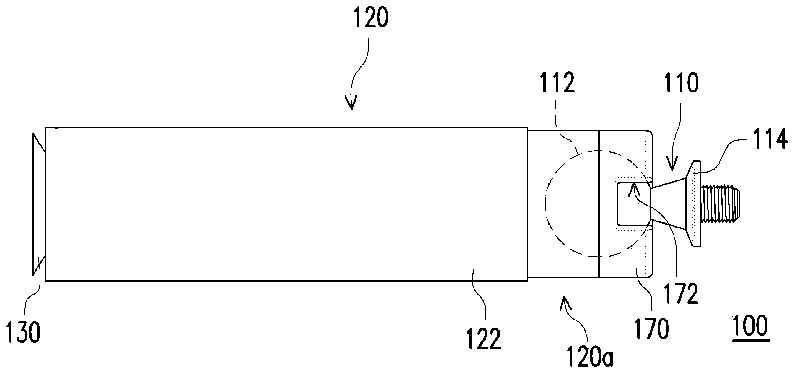
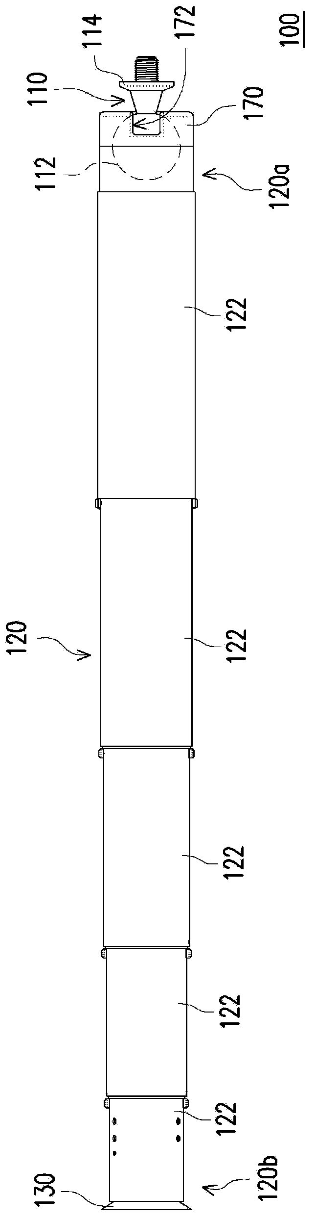
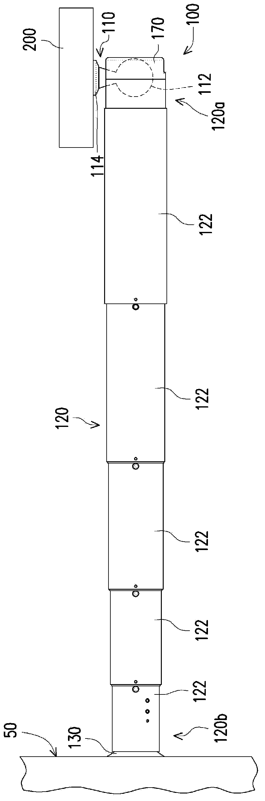
[0069] figure 1 It is a side view of a tripod according to an embodiment of the present invention. figure 2 yes figure 1 Schematic diagram of the elongation of the tripod. image 3 yes figure 2 Schematic diagram of the tripod applied to the projection setup. Please refer to Figure 1 to Figure 3 , the tripod 100 of this embodiment is used for a projection device 200 . The stand 100 includes a connecting piece 110 , a telescopic component 120 and a suction cup 130 . The connecting member 110 is used for connec...


PUM


Abstract

The invention relates to a foot stand which is applied to a projection device. The foot stand comprises a connecting member, a telescopic assembly, a suction disc and a pusher, wherein the connecting member is used for being connected with the projection device and is provided with a spherical joint; the telescopic assembly is provided with a first end part and a second end part which are opposite to each other; the first end part is rotatably connected to the spherical joint; the telescopic assembly comprises at least two sliding parts which are arranged in a mutual sliding manner; the two sliding parts are used for sliding relatively, so as to change the length of the telescopic assembly; the suction disc is fixedly arranged at the second end part; the pusher is arranged at the second end part in a sliding manner; when the pusher is located at a first position, the pusher is far away from the suction disc; when the pusher is located at a second position, the pusher pushes the suction disc, so as to squeeze out air between the suction disc and a surface, and thus, the suction disc is adsorbed to the surface.

Description

technical field [0001] The invention relates to a tripod, and in particular to a tripod of a projection device. Background technique [0002] The projection device can project images on a larger screen so that more people can watch the content displayed on the screen at the same time, so it is often used in companies, schools, families and other occasions. With the advancement of science and technology, various types of electronic products are developing toward high speed, high performance, thinness and shortness. Under this trend, multimedia pico projectors (or mini projectors) have gradually become the future personal The mainstream of the digital market. In addition to placing the projection device on the desktop for use, the user can also use an additional fixing mechanism to fix the projection device on structures such as ceilings or walls. However, most of the fixing methods of the known fixing mechanisms are labor-intensive and time-consuming, and it is difficult to...

Claims


Application Information

Patent Timeline
IPC IPC(8): F16M13/02F16M11/14G03B21/54
Inventor 陈韦如陈家典
Owner CORETRONIC
Why Eureka
Try Eureka