Low-voltage detection device

A technology of communication detection and low-voltage centralized copying, which is applied in measuring devices, measuring electrical variables, signal transmission systems, etc., can solve problems such as time-consuming and laborious, difficult to locate faults, and cannot be reproduced, and achieve the effect of easy use

Active Publication Date: 2014-10-15
ZHUHAI RUNKE ELECTRIC POWER EQUIP
View PDF7 Cites 29 Cited by
  • Summary
  • Abstract
  • Description
  • Claims
  • Application Information

AI Technical Summary

Problems solved by technology

[0002] With the continuous promotion of the use of centralized copying systems, many problems in the use process are gradually exposed, mainly manifested in the low reliability of copying, slow communication speed, etc.
These problems are largely caused by the non-communication specificity and openness of the power line. The access of a large number of electrical equipment introduces noise signals of various characteristics at the same time, and has a certain degree of randomness, which leads to impedance and attenuation time. Denaturation, which increases the uncertainty and reduces the reliability of power carrier communication
After a communication failure occurs in the collection terminal equipment during on-site operation, due to the limited professional skills of the on-site maintenance personnel and the lack of professional maintenance tools, it is usually difficult to determine the cause of the failure on site, and it needs to be removed and sent for repair, which is time-consuming
Some communication failures are caused by on-site electromagnetic environment factors, and the on-site situation cannot be reproduced after repairing
It is difficult to locate the fault and deal with it, especially the fault of carrier communication. The on-site personnel are almost at a loss for it. They can neither determine the communication capability of the carrier module nor know whether the electromagnetic environment on the site has an impact on the carrier communication. The carrier module is often replaced. problem persists after

Method used


Image

  • Low-voltage detection device
  • Low-voltage detection device
  • Low-voltage detection device

Examples


Embodiment Construction

[0017] The following will clearly and completely describe the technical solutions in the embodiments of the present invention with reference to the accompanying drawings in the embodiments of the present invention. Obviously, the described embodiments are only some of the embodiments of the present invention, not all of them. Based on the embodiments of the present invention, all other embodiments obtained by persons of ordinary skill in the art without making creative efforts belong to the protection scope of the present invention.

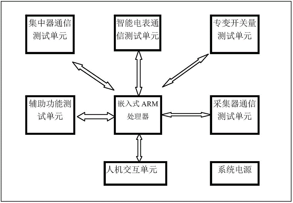
[0018] Such as figure 1 As shown, the low-voltage centralized reading communication detection device includes a concentrator communication test unit, a smart meter communication test unit, a special variable switch test unit, a collector communication test unit, an auxiliary function test unit, an embedded ARM processor, and a human-computer interaction unit. . The embedded ARM processor is respectively electrically connected with the concentrat...


PUM


Abstract

The invention provides a low-voltage concentrated meter reading communication detection device comprising an analog circuit and a digital circuit. The analog circuit comprises power frequency isolation signal coupling, band-pass filtering, carrier signal power detection, a program-controlled local oscillator, AD sampling, a concentrator module, an analog meter module and a power control module. The digital circuit comprises system data memory, an embedded computer software and hardware system, buttons, a display module and a non-carrier communication port. The low-voltage concentrated meter reading communication detection device is an onsite portable tool which is light and convenient and easy to use so that measurement of communication functions, communication capacity and onsite power line electromagnetic environments can be effectively performed on various acquisition devices like a special transformer acquisition terminal, a concentrator, a collector and an electric energy meter, and a local communication problem of an acquisition terminal system can be solved onsite.

Description

technical field [0001] The invention relates to the technical field of power carrier communication, in particular to a low-voltage centralized copy communication detection device. Background technique [0002] With the continuous promotion of the use of centralized copying system, many problems in the use process are gradually exposed, mainly manifested as low copying reliability, slow communication speed and so on. These problems are largely caused by the non-communication specificity and openness of the power line. The access of a large number of electrical equipment introduces noise signals of various characteristics at the same time, and has a certain degree of randomness, which leads to impedance and attenuation time. Denaturation increases the uncertainty and reduces the reliability of power carrier communication. After a communication failure occurs in the collection terminal equipment during on-site operation, it is usually difficult to determine the cause of the fa...

Claims


Application Information

Patent Timeline
Patent Type & Authority Applications(China)
IPC IPC(8): H04B17/00G08C25/00H04B3/54G01R35/04
Inventor 许任阳
Owner ZHUHAI RUNKE ELECTRIC POWER EQUIP
Why Eureka
Try Eureka