LED ceiling lamp

An LED ceiling lamp and lampshade technology, which is applied to the loss prevention measures of lighting devices, lighting and heating equipment, point light sources, etc. The effect of installation, reduced thickness and easy replacement

Active Publication Date: 2014-10-22
UP SHINE LIGHTING CO
View PDF6 Cites 4 Cited by
  • Summary
  • Abstract
  • Description
  • Claims
  • Application Information

AI Technical Summary

Problems solved by technology

[0002] Existing LED ceiling lamps have a part of the middle area, or a part of the area next to the LED ceiling lamp has no light output, so that the light cannot be fully illuminated, resulting in a waste of part of the light source
The power supply is the part with the shortest service life of the entire LED ceiling lamp. The replacement of the power supply will prolong the life of the entire LED ceiling lamp. The existing LED ceiling lamps cannot replace the power supply easily and conveniently, which also affects the service life of the entire LED ceiling lamp.
Existing LED ceiling lamps either do not have waterproof function, or are usually waterproofed through a silicone ring. This waterproof method cannot be airtight, and the rubber strip is easy to age and fail, and the waterproof effect is not good.
The overall structure of the existing LED ceiling lamp is relatively thick, if there is an ultra-thin LED ceiling lamp, it can better meet the needs of the market

Method used


Image

  • LED ceiling lamp
  • LED ceiling lamp
  • LED ceiling lamp

Examples


Embodiment Construction

[0021] The present invention will be further described below in conjunction with the accompanying drawings and embodiments.

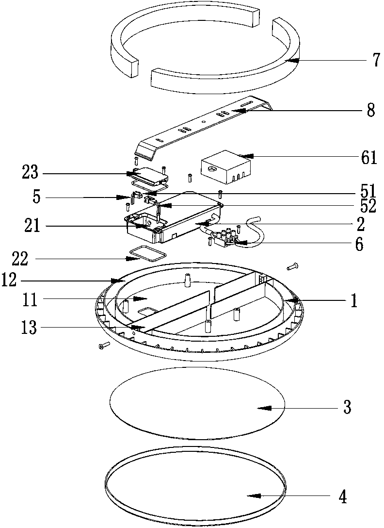
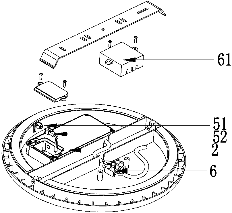
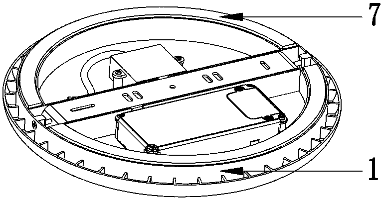
[0022] combine figure 1 As shown, the LED ceiling lamp includes an installation chassis 1 , a power supply 2 , a lamp panel 3 , a lampshade 4 , a first connector 5 , a second connector 6 , a shock-absorbing pad 7 , and a bracket 8 . The lower end of the installation chassis 1 is provided with a connection groove 11, a shock pad installation groove 12, and a bracket installation groove 13, which are respectively used for installing the power supply 2, the shock pad 7, and the bracket 8. All are installed in the installation groove of the installation chassis 1, such a design is convenient to control the thickness of the entire LED ceiling lamp, and the LED ceiling lamp can be made thinner. The bracket 8 is connected to the bracket installation groove 13, and the bracket 8 is fixed on the installation chassis 1 by screws. When installing, the bracket 8 i...


PUM


Abstract

The invention discloses an LED ceiling lamp, comprising an installing base plate, a replaceable power supply, a lamp panel which can give out light, a diaphanous lampshade, a first connector and a second connector, wherein the lower end of the installing base plate is provided with a connecting groove, the power supply is connected to the connecting groove, the lampshade and the installing base plate are connected and form a lamp cavity which can accommodate the lamp panel, the lamp panel is connected to the upper end of the installing base plate and positioned in the lamp cavity, the joint of the lampshade and the installing base plate is provided with a waterproof structure, one end of the power supply is connected to the lamp panel through the first connector while the other end of the power supply is connected to the second connector, the first and second connectors are both connected to the connecting groove, and both the first and second connectors are provided with waterproof structures. The LED ceiling lamp is waterproof; meanwhile the power supply can be simply mounted and dismounted, thus being convenient to replace the power supply and improving service life of the LED ceiling lamp; all parts are connected to the groove of the installing base plate, which can reduce thickness of the whole LED ceiling lamp.

Description

technical field [0001] The invention relates to the technical field of lamps, in particular to an LED ceiling lamp. Background technique [0002] Existing LED ceiling lamps have a part of the middle area, or a part of the area next to the LED ceiling lamp has no light output, so that the light cannot be fully illuminated, resulting in a waste of part of the light source. The power supply is the part with the shortest service life of the entire LED ceiling lamp. The replacement of the power supply will prolong the life of the entire LED ceiling lamp. The existing LED ceiling lamps cannot easily and conveniently replace the power supply, which also affects the service life of the entire LED ceiling lamp. Existing LED ceiling lamps either do not have a waterproof function, or waterproofing is generally done through a silicone ring. This waterproofing method cannot be airtight, and the rubber strip is easy to age and fail, and the waterproof effect is not good. The overall stru...

Claims


Application Information

Patent Timeline
IPC IPC(8): F21S8/04F21V17/00F21V31/00F21V15/04F21Y101/02
Inventor 谢祖华王武孔玉申
Owner UP SHINE LIGHTING CO
Why Eureka
Try Eureka