
Fully automatic sample-injection mechanism of flow cytometer

A flow cytometer, fully automatic technology, applied in the field of flow cytometer automatic sampling mechanism, can solve the problems of destroying test tubes and sampling needles, single swing direction, low sampling accuracy, etc., to save equipment costs, horizontal movement The effect of stabilization and improvement of sampling accuracy

Active Publication Date: 2014-10-22
SUZHOU RIHE TECH
View PDF5 Cites 13 Cited by
  • Summary
  • Abstract
  • Description
  • Claims
  • Application Information

AI Technical Summary

Problems solved by technology

[0003] In the prior art, the flow cytometer has an important link before measurement, that is, the sampling link. For the sampling mechanism of the flow cytometer in the prior art, a The driving motor drives the sampling needle to take samples, which not only increases the overall space occupied by the flow cytometer, but also directly drives the driving motor, which may easily cause unstable movement of the sampling needle and low sampling accuracy; at the same time, because the flow cytometer samples from the test tube, However, the caliber of the test tubes used in the prior art is generally narrow, and it is impossible to add a stirring mechanism wh

Method used


Image

  • Fully automatic sample-injection mechanism of flow cytometer
  • Fully automatic sample-injection mechanism of flow cytometer
  • Fully automatic sample-injection mechanism of flow cytometer

Examples


Embodiment Construction

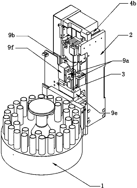
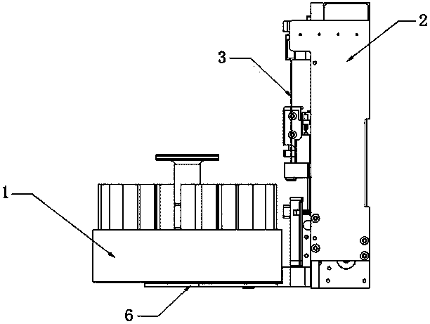
[0028] Example: refer to Figures 1 to 7 As shown, a fully automatic sample feeding mechanism for a flow cytometer includes a rotating disk 1 with a number of test tube installation holes distributed radially, an X-direction driving mechanism arranged on a fixed plate 2 on one side of the rotating disk 1, and a drive mechanism connected to the X-direction The sampling needle 3 connected to the drive mechanism and the Z-direction drive mechanism, the X-direction drive mechanism includes an X-direction slide rail 4a arranged on the fixed plate 2, a sampling needle drive plate 4b provided on the X-direction slide rail 4a, and a drive plate for driving Sampling needle drive plate 4b is a steering gear linkage driving mechanism that horizontally reciprocates along the X-direction slide rail 4a. The two-stage connecting rod 4c-2 connected with the plate 2 and the other end connected with the steering gear 4c-1; at the same time, the Z-direction driving mechanism is connected with th...


PUM


Abstract

The invention discloses a fully automatic sample-injection mechanism of a flow cytometer. The fully automatic sample-injection mechanism comprises a rotation disc radially provided with several test tubes, an X-direction driving mechanism arranged on a fixing plate at one side of the rotation disc, a sampling pin and a Z-direction driving mechanism, wherein the sampling pin and the Z-direction driving mechanism are connected to the X-direction driving mechanism. The X-direction driving mechanism comprises an X-direction sliding rail arranged on the fixing plate, a sampling pin driving plate arranged on the X-direction sliding rail, and a steering engine connection rod driving mechanism for driving the sampling pin driving plate to carry out horizontal reciprocating motion along the sliding rail. The Z-direction driving mechanism is connected to a base of the rotation disc by a connection plate and drives the rotation disc to carry out vertical reciprocating motion along the Z direction. The connection plate is connected to the base by rotation telescopic shafts arranged along the rotation disc radial direction. Through the X-direction sliding rail on the fixing plate and the steering engine connection rod driving mechanism, the sampling pin arranged on the sampling pin driving plate is driven to carry out horizontal reciprocating motion along the X-direction sliding rail. The fully automatic sample-injection mechanism has a simple structure and a small occupation space and realizes stable sampling pin horizontal-motion.

Description

technical field [0001] The invention relates to a sample feeding mechanism, in particular to a fully automatic sample feeding mechanism for a flow cytometer. Background technique [0002] Flow cytometry is a device for automatic analysis and sorting of cells. It can quickly measure, store and display a series of important biophysical and biochemical characteristic parameters of dispersed cells suspended in liquid, and can sort out specified cell subpopulations according to the preselected parameter range. [0003] The flow cytometer in the prior art has an important link before measurement, that is, the sampling link. For the sampling mechanism of the flow cytometer in the prior art, a driving motor is used to drive the sampling needle for sampling, which not only increases the overall flow cytometer Occupies space, and is directly driven by a drive motor, which may easily cause unstable movement of the sampling needle and low sampling accuracy; at the same time, because th...

Claims


Application Information

Patent Timeline
IPC IPC(8): G01N35/10G01N15/14
Inventor 蔡春午李藏珍李爱国
Owner SUZHOU RIHE TECH
Learn More