Furniture hinge

A furniture and hinge technology, applied in the field of furniture hinges, can solve complex and expensive problems

Active Publication Date: 2014-10-22
JULIUS BLUM GMBH
View PDF10 Cites 1 Cited by
  • Summary
  • Abstract
  • Description
  • Claims
  • Application Information

AI Technical Summary

Problems solved by technology

The hinge cups, hinge rods and hinge arms are therefore supported by s

Method used


Image

  • Furniture hinge
  • Furniture hinge
  • Furniture hinge

Examples


Embodiment Construction

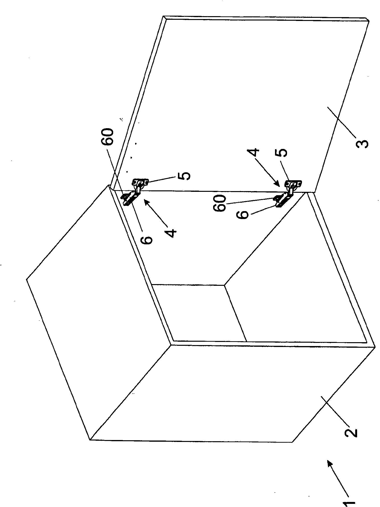
[0023] figure 1 A perspective view of a piece of furniture 1 is shown, in which a door 3 is mounted pivotably via a furniture hinge 4 relative to a furniture body 2 . In a known manner, the furniture hinge 4 has a hinge cup 5 which is articulatedly connected to a hinge arm 6 . The hinge cup 6 can be releasably engaged with a mounting plate 60 to be fixed on the furniture body 2 by means of a snap mechanism in a known manner. The furniture hinges 4 each comprise at least one (not shown here) linear damper 7 for damping the hinge movement, wherein the linear damper 7 is arranged on the outside of the hinge cup 5 and is arranged on the hinge cup 5 in the installed position. Beneath the fastening flange 8 of the cup 5 , the hinge cup 5 can be arranged together with at least one linear damper 7 arranged thereon in a preferably cylindrical bore of the door 3 and within the imaginary bore diameter of the bore.

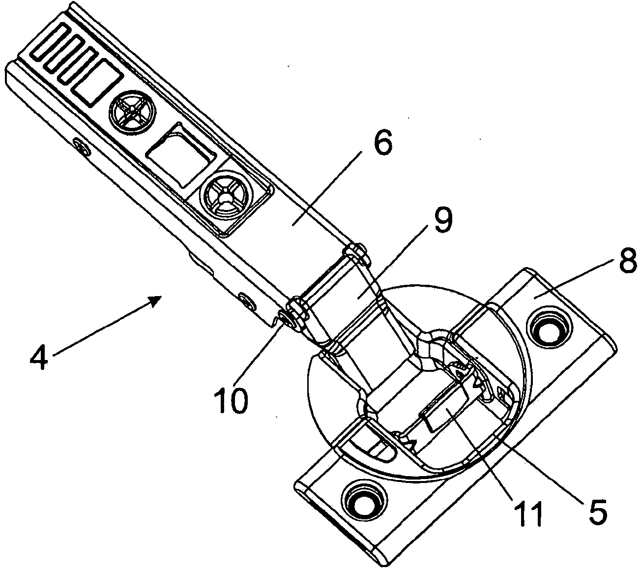
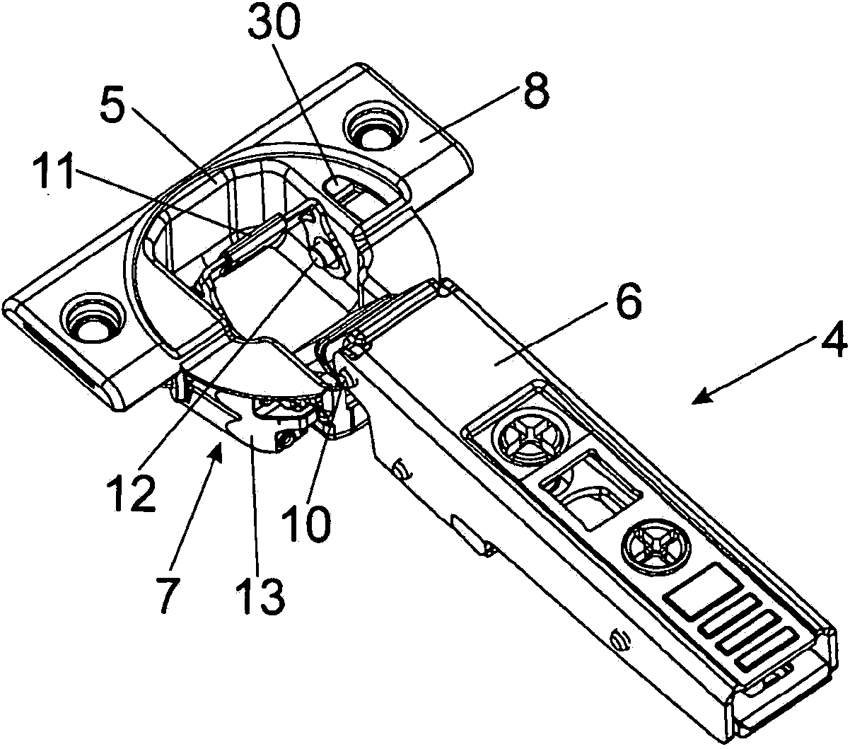
[0024] Figure 2a and 2b The furniture hinge 4 is shown in two diffe...


PUM

PropertyMeasurementUnit
Acute angleaaaaaaaaaa

Abstract

The invention relates to a furniture hinge (4) comprising a hinge arm (6) having a longitudinal axis (X), a hinge cup (5) that is connected to the hinge arm (6) and is mounted such as to be pivotable relative to the hinge arm (6) between a closed position and an open position, and further comprising a linear damper (7) having a linear damping stroke (Y) for damping a movement of the furniture hinge (4), wherein the linear damper (7) is arranged at the hinge cup (5) and, jointly therewith, can be arranged within a bore of a furniture item (3) in the installed position, wherein in the open position of the furniture hinge (4) in a plan view, the direction of the linear damping stroke (Y) of the linear damper (7) runs at an acute angle (alpha) relative to the longitudinal axis (X) of the hinge arm (6), the acute angle (alpha) being between 3° and 20°.

Description

technical field [0001] The invention relates to a furniture hinge having a hinge arm with a longitudinal axis, a hinge cup connected to the hinge arm and a linear damper with a linear damping stroke, the hinge cup being able to be closed in relation to the hinge arm Mounted pivotally between a position and an open position, the linear damper is used for damping the movement of the furniture hinge, wherein the linear damper is arranged on the hinge cup and can be arranged together with the hinge cup on one of the furniture parts in the installed position. the inside of the hole. [0002] Furthermore, the invention relates to a piece of furniture having a furniture body and a movable furniture part, which is mounted pivotably relative to the furniture body via at least one furniture hinge of the type described. Background technique [0003] The damping action of a linear damper is primarily based on the flow resistance of the damping fluid present in the fluid chamber. Dampi...

Claims


Application Information

Patent Timeline
IPC IPC(8): E05F5/00
CPCE05Y2900/20E05Y2201/256E05Y2201/264E05Y2201/21E05F5/006E05Y2201/624E05Y2201/22A47B96/00E05D3/06E05D11/08E05F3/14E05F5/00E05F5/02E05F5/10E05D7/00
Inventor A·霍尔茨阿普费尔
Owner JULIUS BLUM GMBH
Why Eureka
Try Eureka