Anti-rebound and anti-off door stop

A technology of collision head and elastic parts, applied in the field of door collision, can solve the problems of affecting the service life of door collision and easily damaged door collision, etc.

Pending Publication Date: 2020-05-01
张秦鸣
View PDF1 Cites 0 Cited by
  • Summary
  • Abstract
  • Description
  • Claims
  • Application Information

AI Technical Summary

Problems solved by technology

[0002] When the door is opened, in order to prevent the door from turning freely under the influence of external force, a door touch is usually set between the lower back of the door and the wall. The current door touch mainly uses the magnetic force to attract the two parts of the suction seat and the suction column together. Fix the door, if the door rotates fast during suction, there will be a knocking sound between the suction seat and the suction column, and it is easy to damage the door touch and affect the service life of the door touch

Method used


Image

  • Anti-rebound and anti-off door stop
  • Anti-rebound and anti-off door stop
  • Anti-rebound and anti-off door stop

Examples


Embodiment 1

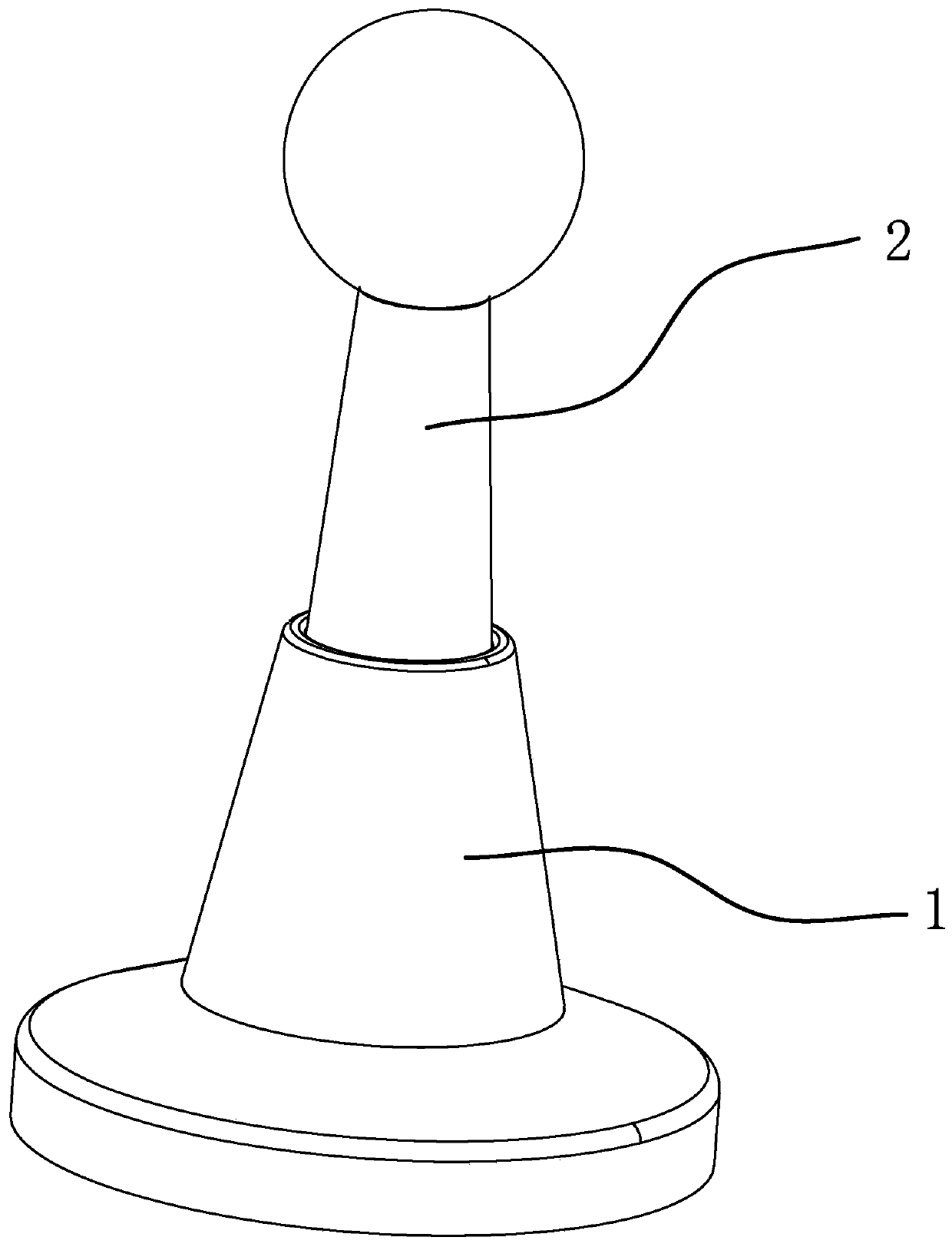
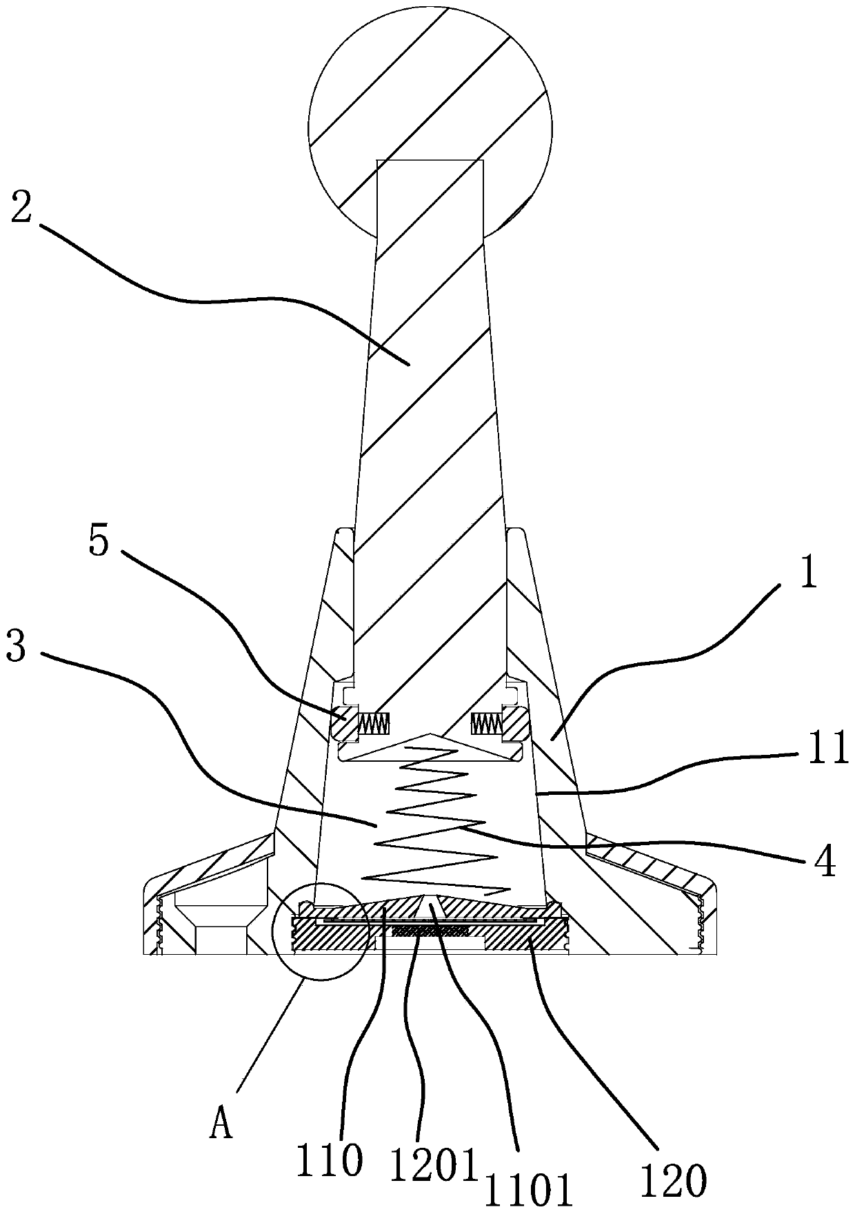
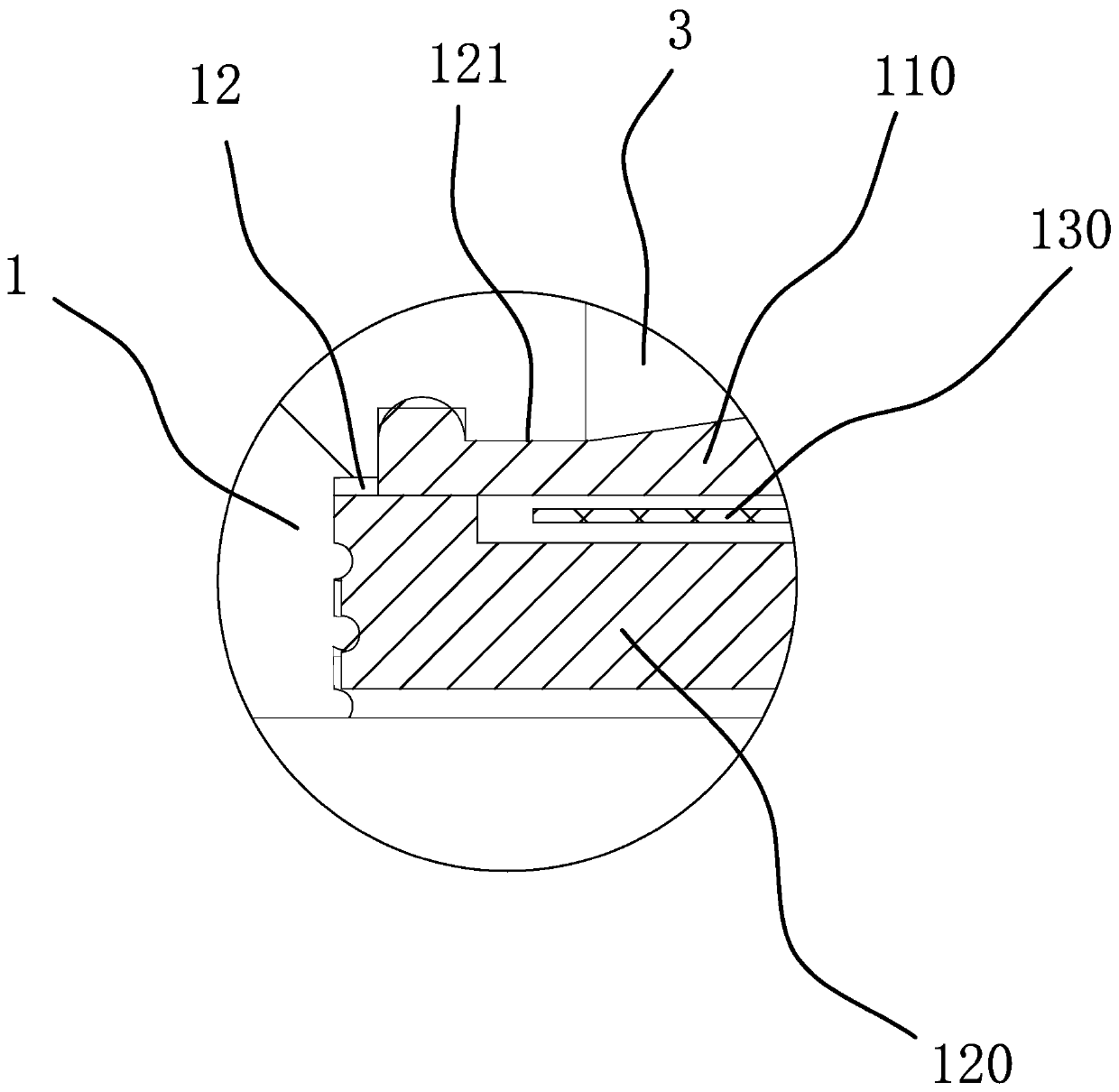
[0063] Such as Figure 1-3As shown, the bulletproof door bumper includes a seat body 1 and a columnar collision head 2, the seat body 1 has a stroke chamber 3, the inner end of the collision head 2 is slidingly fitted in the stroke chamber 3, and the inner end of the collision head 2 is in contact with the stroke chamber 3. A damping member 4 is provided between the seat body 1 to prevent the collision head 2 from sliding toward the interior of the seat body 1. The collision head 2 is provided with a friction member 5 that can move radially along the collision head 2. The friction member 5 can be connected with the stroke cavity 3 The inner wall is against, and damping oil or lubricating oil is coated between the friction member 5 and the inner wall of the stroke chamber 3 to make the door bumper work more stable. When the collision head 2 slides toward the outside of the seat body 1, the friction member 5 and the stroke chamber The pressing force between the inner walls of th...

Embodiment 2

[0066] Such as Figure 4-7 As shown, this embodiment is basically the same as the first embodiment, except that the friction member 5 is ring-shaped and sleeved around the periphery of the collision head 2 , and a fracture 51 is opened on the friction member 5 . By setting the friction member 5 in an annular shape and sleeved on the periphery of the collision head 2, a fracture 51 is provided on the friction member 5, so that the friction member 5 is similar to a piston ring, and the design of the fracture 51 can ensure that the friction member 5 itself can be elastically deformed It has a tendency of outward expansion and a simplified structure. The outer peripheral surface of the collision head 2 has a limit ring groove 21 extending in the circumferential direction, and the friction member 5 is located in the limit ring groove 21 . Specifically, a limit ring groove 21 extending in the circumferential direction is set on the collision head 2, so that the friction member 5 is...

Embodiment 3

[0069] Such as Figure 8-12 As shown, the present embodiment is basically the same as the second embodiment, the difference is that there are two friction members 5 in the shape of circular arcs, and the two friction members 5 are sequentially arranged on the periphery of the collision head 2 along the circumferential direction. A pre-compressed elastic piece 6 is provided between the friction pieces 5 , and the two ends of the elastic piece 6 respectively abut against two adjacent friction pieces 5 . By arranging two friction members 5 in an arc shape, the two friction members 5 are successively arranged on the periphery of the collision head 2 along the circumferential direction, and elastic members 1-6 are arranged between adjacent two friction members 5, so that A plurality of elastic members 1 can work together to eject the friction member 5 outward in the radial direction, so as to ensure the force between the friction member 5 and the side wall of the stroke chamber 3 ....


PUM


Abstract

The invention provides an anti-rebound and anti-off door stop and belongs to the technical field of door stops. Through the anti-rebound and anti-off door stop, the technical problem that an existingdoor stop structure is likely to rebound a door body when impact force of the door body is large is solved. The anti-rebound and anti-off door stop comprises a base and a collision head. The base is internally provided with a travel cavity. The inner end of the collision head is in sliding fit with the interior of the travel cavity. A damping part is arranged between the inner end of the collisionhead and the base. The collision head is provided with friction pieces abutting against the inner sidewall of the travel cavity. When the collision head slides to the exterior of the base, pressing force of the friction pieces acting on the inner sidewall of the travel cavity gradually increases. When the collision head slides to the interior of the base, pressing force of the friction pieces acting on the inner sidewall of the travel cavity gradually decreases. The anti-rebound and anti-off door stop provided by the invention can effectively prevent the door body from being rebounded and getting away from the door stop.

Description

technical field [0001] The invention belongs to the technical field of door touches, and relates to a bulletproof door touch. Background technique [0002] When the door is opened, in order to prevent the door from turning freely under the influence of external force, a door touch is usually set between the lower back of the door and the wall. The current door touch mainly uses the magnetic force to attract the two parts of the suction seat and the suction column together. Fix the door, if the door rotates faster during suction, there will be a knocking sound between the suction seat and the suction column, and it is easy to damage the door touch and affect the service life of the door touch. In order to solve this problem, technicians in the field add buffer components such as springs to the door touch, and absorb the impact of the door collision through the deformation of the buffer components to achieve the effect of silence. [0003] The applicant has previously develop...

Claims


Application Information

Patent Timeline
Patent Type & Authority Applications(China)
IPC IPC(8): E05C17/56E05F5/06
CPCE05C17/56E05F5/06
Inventor 张秦鸣
Owner 张秦鸣
Why Eureka
Try Eureka