Sliding closure panel assembly

Active Publication Date: 2007-01-02
AUTOMOTIVE COMPONENTS HOLDINGS +1
View PDF69 Cites 27 Cited by
  • Summary
  • Abstract
  • Description
  • Claims
  • Application Information

AI Technical Summary

Benefits of technology

[0008]In accordance with the invention, one of the first surface features on at least one guide rail is preferably positioned relative to the opening such that the one of the first surface features also engages a different one of the second surface features on the sliding panel as the sliding panel is moved into the fully-open position, whereupon the sliding panel is again displaced toward the fixed panel to thereby at least partially compress a portion of the seal. In this manner, the sliding panel is maintained in the fully-open position by the resilient partial compression of the seal while advantageously reducing noise that might otherwise result from relative l

Problems solved by technology

Unfortunately, the lateral force exerted on the sliding panel by the guide rails typically generates a friction drag that resists free and easy movement of the sli

Method used


Image

  • Sliding closure panel assembly
  • Sliding closure panel assembly

Examples


Embodiment Construction

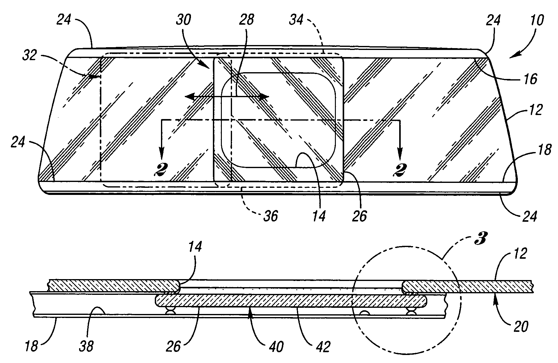
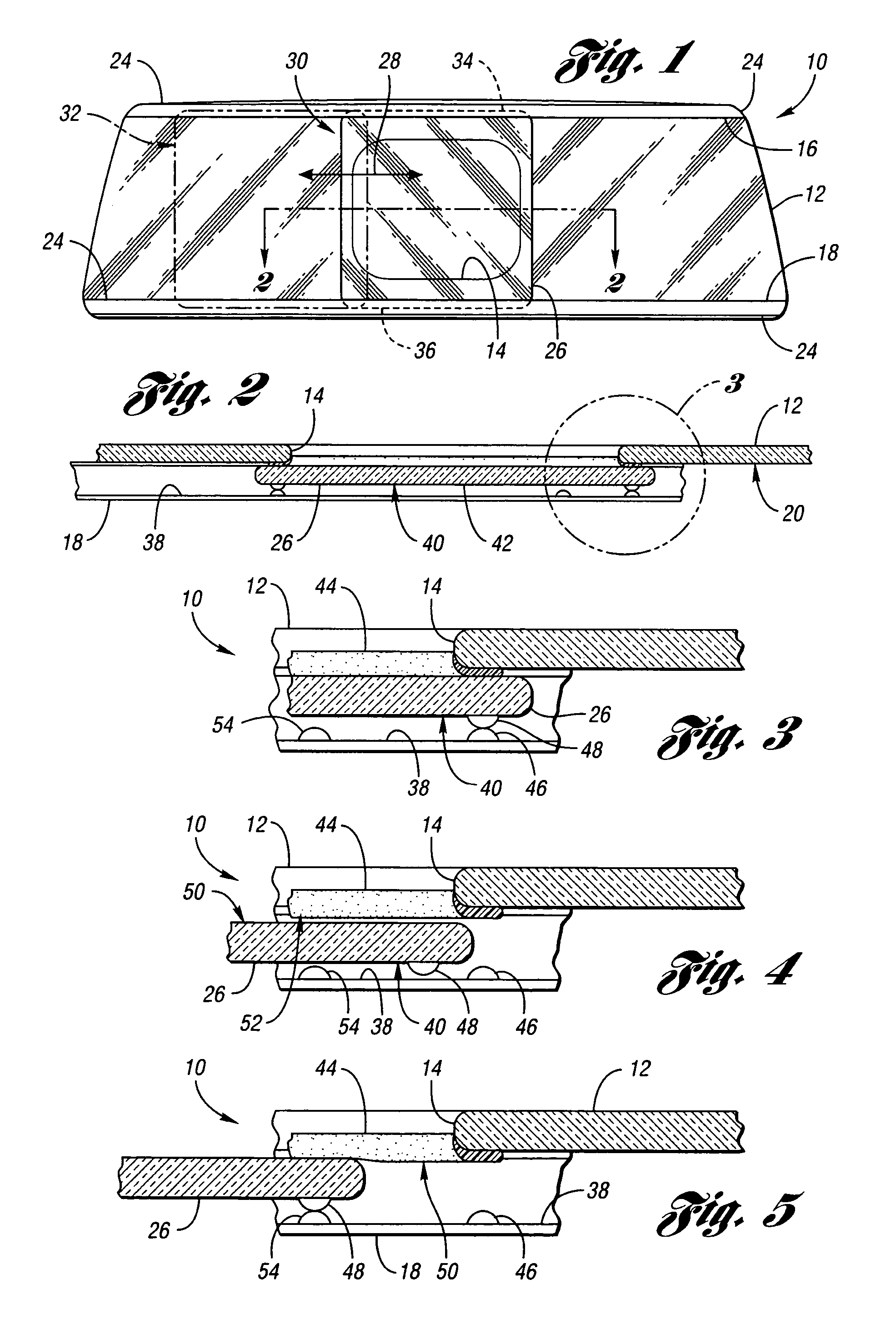
[0017]Referring to FIG. 1, an exemplary closure panel assembly 10 in accordance with the invention, as may be used as the backlight for a passenger vehicle such as a light truck (not shown), generally includes a fixed panel 12 which defines an opening 14. The fixed panel 12 is preferably formed of a relatively rigid material and, where desired, may be formed of a transparent or translucent material such as a tempered glass, as illustrated in the Figure. The opening 14 thus provides access to the interior / exterior of the passenger compartment of the vehicle.

[0018]The assembly 10 includes a pair of support or guide rails 16, 18 affixed to the fixed panel 12 on generally opposite sides of the opening 14. While the invention contemplates affixing or attaching the guide rails 16, 18 to the fixed panel 12 in any suitable manner, in the assembly 10 illustrated in the Drawings, the guide rails 16, 18 are conveniently affixed to a first face 20 of the fixed panel 12 with a pressure-sensitive...


PUM


Abstract

A closure panel assembly (10) includes a fixed panel (12) defining an opening (14), a pair of guide rails (16,18) disposed on opposite sides of the opening, and a sliding panel (26) supported by the guide rails for movement between a closed position over the opening and an open position. Cooperating surface features (46,48) on at least one guide rail and the sliding panel engage one another when the sliding panel is moved to the closed position, to laterally displace the sliding panel toward the fixed panel and thereby compress a seal (44) disposed therebetween. Additional surface features (54) on the guide rail similarly engage the sliding panel's surface features to displace the sliding panel toward the fixed panel when the sliding panel is in a partially-open position, to thereby at least partially compress the seal and create a frictional drag on the sliding panel resisting further movement.

Description

CROSS-REFERENCE TO RELATED APPLICATIONS[0001]This application claims benefit of U.S. provisional patent application No. 60 / 429,805, filed Nov. 27, 2002, the disclosure of which is hereby incorporated herein by reference.FIELD OF THE INVENTION[0002]The invention relates generally to a closure panel assembly in which a movable or “sliding” panel is urged against a stationary or “fixed” panel to thereby compress an air or moisture seal disposed between opposed surfaces on the sliding panel and the fixed panel.BACKGROUND OF THE INVENTION[0003]A closure panel assembly, as is typically employed to define a rearward-facing window or “backlite” for a passenger compartment of a light truck, generally includes a fixed glass panel in which an opening is defined, and a sliding glass panel that moves along a pair of support or guide rails between a closed position and an open position relative to the opening. A compression seal is disposed between the fixed and sliding panels, for example, by mo...

Claims


Application Information

Patent Timeline
IPC IPC(8): E05D15/06B60J1/18B60J10/04E06B3/46
CPCB60J1/1853B60J10/04E06B3/4681B60J10/74
Inventor BOURQUE, JEFFREY GERARDKOLOKOWSKI, PAUL JOSEPHLESLE, MICHAEL JAMESLYKE, LAWRENCE R.PAYTON, JR., THOMAS WILLIAMSAXON, SCOTTTANKSLEY, MARCUSWEINERT, RICK MARK
Owner AUTOMOTIVE COMPONENTS HOLDINGS
Why Eureka
Try Eureka