Magnetic recording medium and magnetic recording and reproducing device
- Summary
- Abstract
- Description
- Claims
- Application Information
AI Technical Summary
Benefits of technology
Problems solved by technology
Method used
Image
Examples
example 1
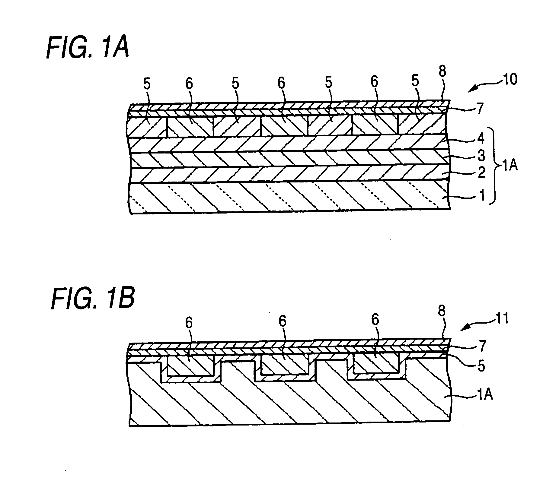
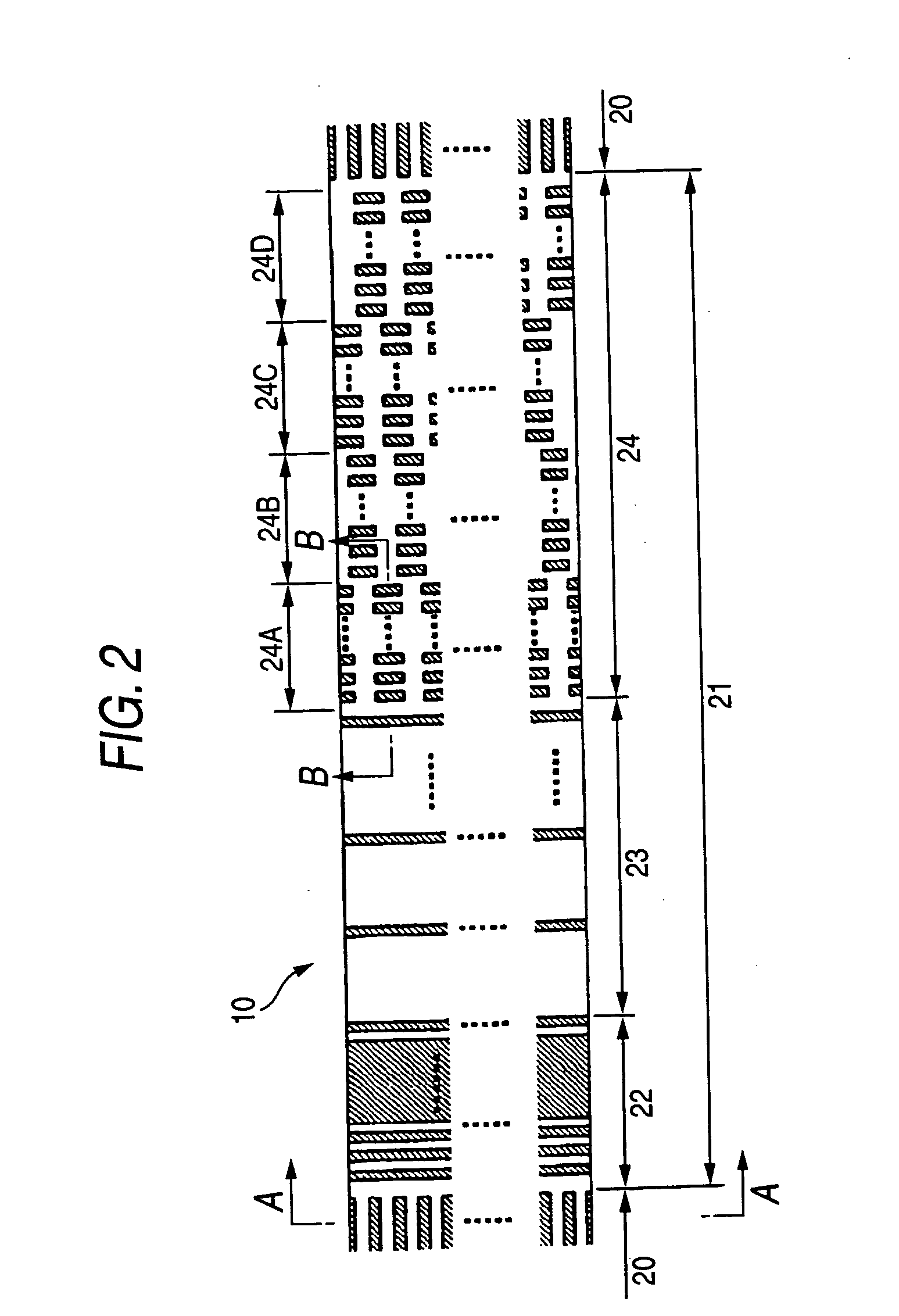
[0104] A non-magnetic layer 6 was formed on the to-be-processed body obtained in the aforementioned manner. First, a film of SiO2 was formed to be 100 nm thick by a sputtering method in the conditions of 500 W in film formation power, 150 W in bias power and 0.3 Pa in Ar gas pressure. Incidentally, the film thickness here means the thickness of a film on a flat surface when the film was formed on the flat surface in parallel. Ion beam etching using Ar gas and having an incident angle of 2° was performed on the to-be-processed body after the non-magnetic layer 6 was formed. Thus, a surplus of SiOs on the magnetic recording layer 5 was removed so that the surface was flattened. The etching was monitored by a mass spectroscope. The flattening was completed as soon as the magnetic recording layer in the servo pattern region 21 began to be detected.
[0105] Incidentally, the surface position of the non-magnetic layer 6 is lower in each data track region 20 than in each servo pattern regio...
example 2
[0111] A magnetic recording medium shown in FIGS. 4A-4B was manufactured in a method similar to that in Example 1. This magnetic recording medium could be manufactured as follows. That is, in the ion beam etching of the non-magnetic layer in Example 1, the ion beam etching had been suspended since the magnetic recording layer 5 in each data track region 20 began to be detected and till the magnetic recording layer 5 in each servo pattern region 21 began to be detected. Thus, flattening was completed.
example 3
[0112] A magnetic recording medium shown in FIGS. 5A-5B was manufactured in a method similar to that in Example 1. This magnetic recording medium could be manufactured as follows. That is, in the ion beam etching of the non-magnetic layer in Example 1, the ion beam etching was once suspended as soon as the magnetic recording layer 5 in each data track region 20 began to be detected. The incident angle was changed from 2° to 90° (90° was an incident angle with which “the etching rate of the magnetic recording layer 5 was higher than the etching rate of the non-magnetic material (SiO2)”), and the ion beam etching was resumed. The ion beam etching was suspended as soon as the magnetic recording layer 5 in each servo pattern region 21 began to be detected. Thus, flattening was completed.
PUM
 Abstract
Description
Claims
Application Information
 - R&D
- Intellectual Property
- Life Sciences
- Materials
- Tech Scout
- Unparalleled Data Quality
- Higher Quality Content
- 60% Fewer Hallucinations
Browse by: Latest US Patents, China's latest patents, Technical Efficacy Thesaurus, Application Domain, Technology Topic, Popular Technical Reports.
© 2025 PatSnap. All rights reserved.Legal|Privacy policy|Modern Slavery Act Transparency Statement|Sitemap|About US| Contact US: help@patsnap.com


