
Hydraulic fracture composition and method

Active Publication Date: 2012-04-05
AQUASMART ENTERPRISES
View PDF2 Cites 27 Cited by
  • Summary
  • Abstract
  • Description
  • Claims
  • Application Information

AI Technical Summary

Benefits of technology

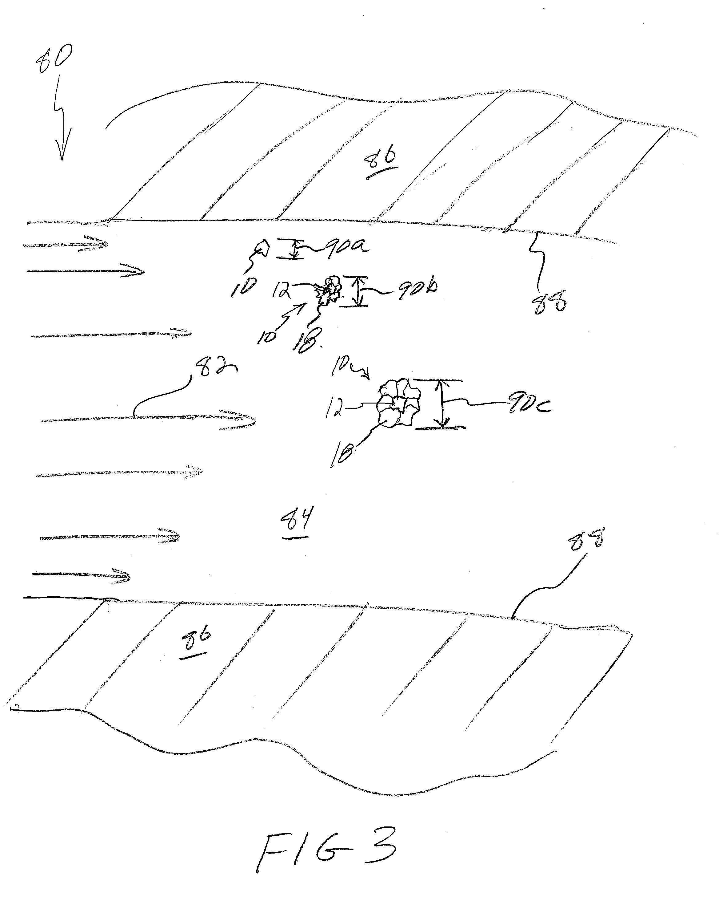
[0009]By virtue of the increased surface area and weight provided to the polymeric powders affixed to the substrate, the surface area, and consequently the frictional drag, is greatly increased, sweeping the material of the invention into a flow of fluid. This greatly decreases the time required to absorb polymers into the fluid.
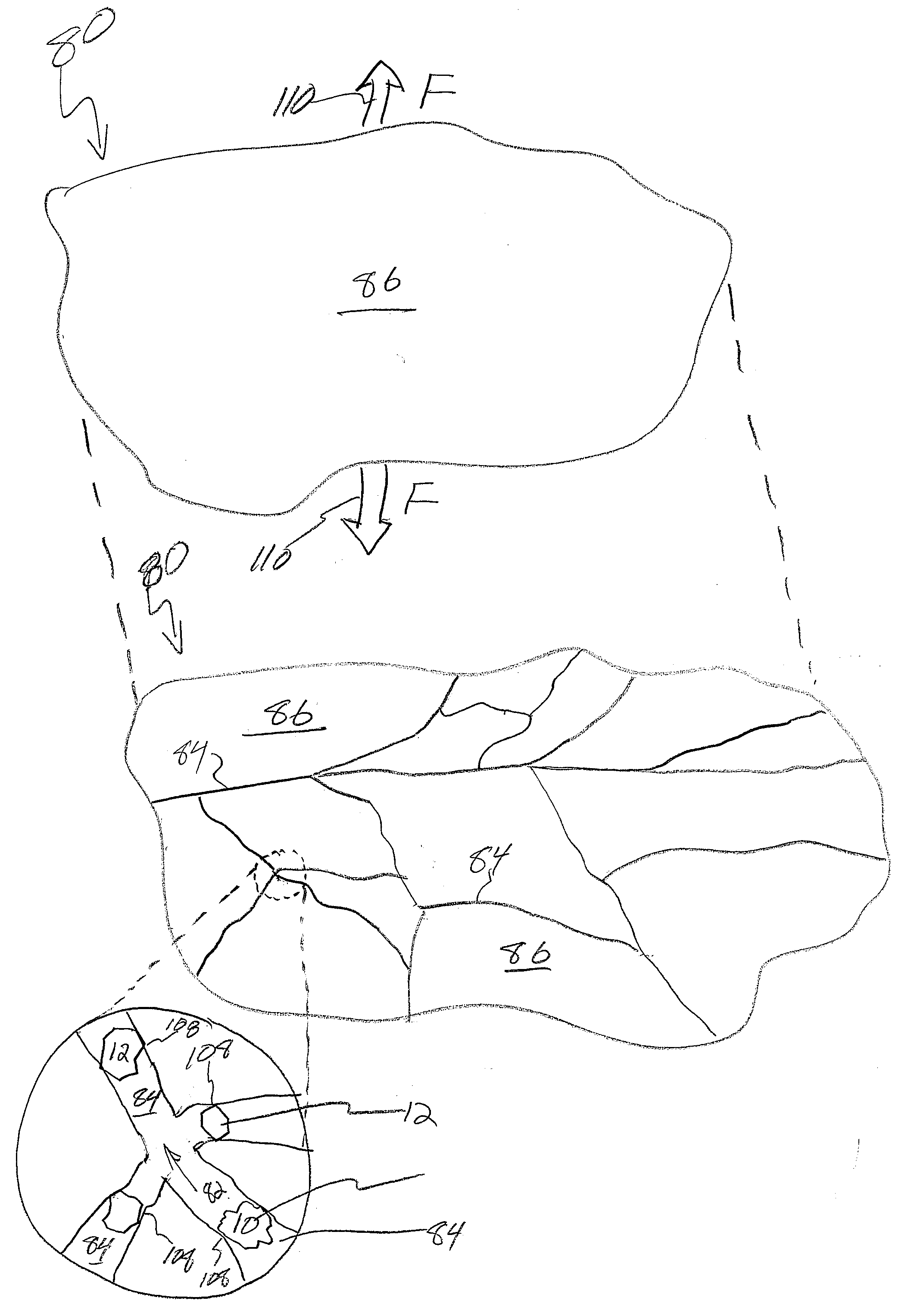
[0033]The particles of the polymer, bound to the substrate, will travel with it in the fluid. Particles of the polymer are thus further directly exposed to water in the fluid during travel with the fluid. The granules, flowing in the fluid, are carried by the hydrodynamic drag of the fluid against the cross-sectional area of the granules coated with the particles of the polymer. The polymer, selected to expand by absorbing water directly from the fluid, increases the area and drag, assisting distribution in the formation by the carrier fluid. The polymer meanwhile operates as a lubricant lubricating the motion of the substrate against the formation during flow of the granules against solid surfaces in the formation, bore, and fracture fissures.

Problems solved by technology

Meanwhile, the cross sectional area presented results in hydrodynamic drag sweeps the composition along with the flow.

Method used


Image

  • Hydraulic fracture composition and method
  • Hydraulic fracture composition and method
  • Hydraulic fracture composition and method

Examples


Embodiment Construction

[0043]It will be readily understood that the components of the present invention, as generally described and illustrated in the drawings herein, could be arranged and designed in a wide variety of different configurations. Thus, the following more detailed description of the embodiments of the system and method of the present invention, as represented in the drawings, is not intended to limit the scope of the invention, as claimed, but is merely representative of various embodiments of the invention. The illustrated embodiments of the invention will be best understood by reference to the drawings, wherein like parts are designated by like numerals throughout.

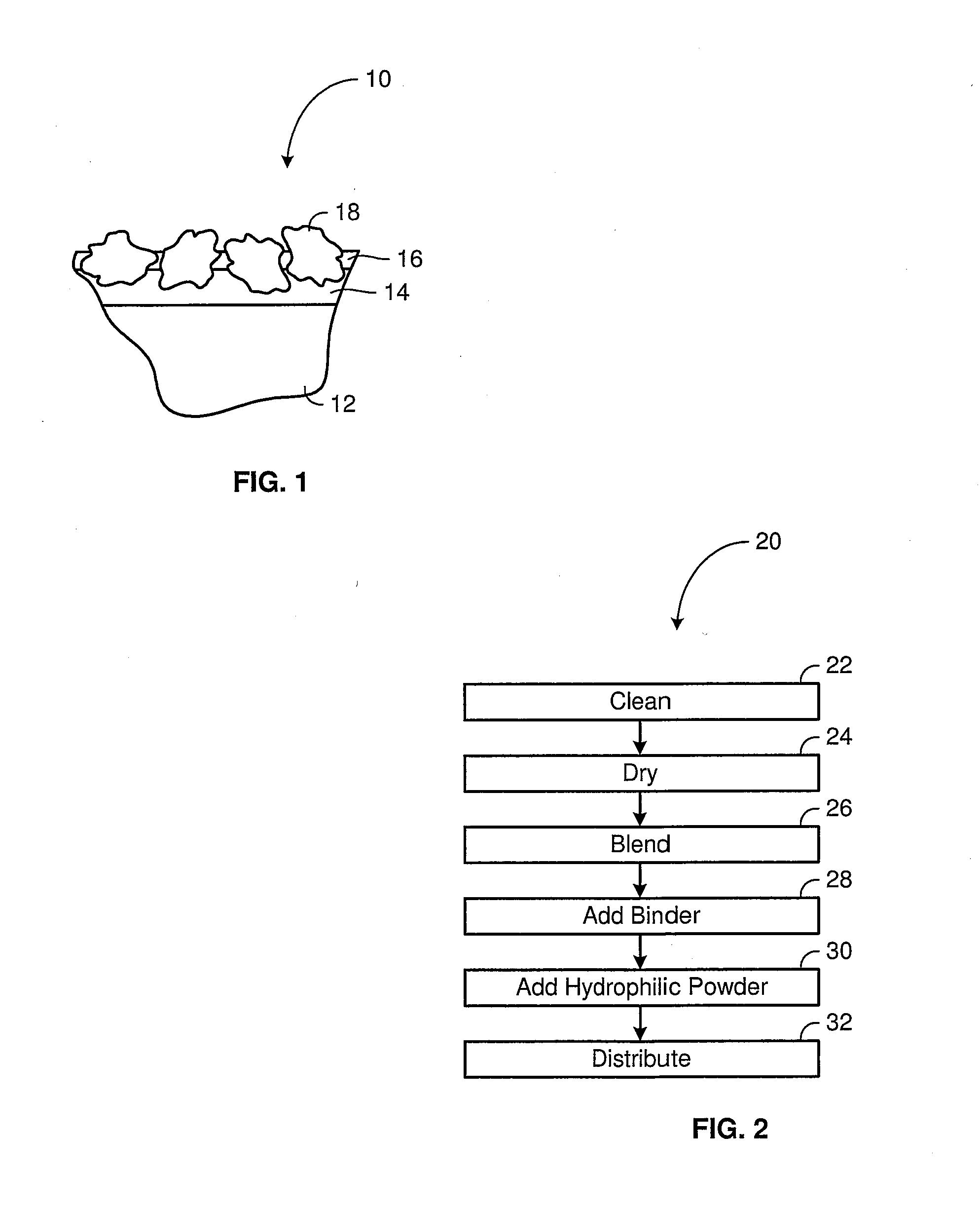
[0044]Referring to FIG. 1, a material 10 in accordance with the invention may include a substrate 12 formed of a suitable material for placement in the vicinity of a fracture region. For example, a substrate may be a particle of sand, ceramic sand, volcanic grit, or other hard material. In some embodiments, a substrate may be fo...


PUM


Abstract

A method for improving the performance of fracturing processes in oil production fields may rely on polymer coated particles carried in the fracturing fluid. The particles may include heavy substrates, such as sand, ceramic sand, or the like coated with polymers selected to absorb water, increasing the area and volume to travel more readily with the flow of fluid without settling out, or allowing the substrate to settle out. Ultimately, the substrate may become lodged in the fissures formed by the pressure or hydraulic fracturing, resulting in propping open of the fissures for improved productivity.

Description

RELATED APPLICATIONS [0001]This application is a continuation-in-part of U.S. patent application Ser. No. 12 / 789,177, filed May 27, 2010 and entitled “HYDRATION MAINTENANCE APPARATUS AND METHOD,” which is a continuation of U.S. patent application Ser. No. 12 / 324,608, now U.S. Pat. No. 7,726,070, issued Jun. 1, 2010 to Thrash and entitled “HYDRATION MAINTENANCE APPARATUS AND METHOD,” which claims the benefit of U.S. Provisional Patent Application Ser. No. 61 / 012,912, filed on Dec. 11, 2007.BACKGROUND[0002]1. The Field of the Invention[0003]This invention relates to oil field and oil well development, and, more particularly, to novel systems and methods for fracturing and propping fissures in oil-bearing formations to increase productivity.[0004]2. The Background Art[0005]Oil well development has over one hundred years of extensive engineering and chemical improvements. Various methods for stimulating production of well bores associated with an oil reservoir have been developed. For e...

Claims


Application Information

Patent Timeline
IPC IPC(8): E21B43/26C09K8/68
CPCC10G2300/1033C09K8/88C09K8/68C10G2300/4037
Inventor HENDRICKSON, CALDERTHRASH, TOMMY K.
Owner AQUASMART ENTERPRISES
Learn More