Storage and drainage planting tank

A planting trough, water storage and drainage technology, applied in automatic watering devices, botanical equipment and methods, container cultivation, etc., can solve the problems of the bottom of the box can not be ventilated, the splicing structure is complicated, and the water volume at the bottom is not easy to control, etc., to achieve splicing structure simple and reliable effect

Active Publication Date: 2017-06-06
GUANGDONG WELL TECH
View PDF21 Cites 0 Cited by
  • Summary
  • Abstract
  • Description
  • Claims
  • Application Information

AI Technical Summary

Problems solved by technology

The splicing structure of traditional spliced ​​planting tanks is relatively complicated or the splicing is not tight. It is inconvenient to control the amount of watering and fertilization of plants, and it is easy to cause insufficient or excessive waste of water or fertilizer. Corruption occurs in water environment
For example, a planting box is disclosed in the Chinese patent specification CN20341665U. The bottom of the planting box is provided with a spacer, the upper part of the spacer is provided with a filter cloth, and one side of the bottom of the box is provided with a drainage device. When the planter is in use, The bottom of the box cannot be ventilated, the roots of the plants are hypoxic, and are prone to corruption, and the bottom of the box cannot be automatically drained, and the water volume at the bottom is difficult to control; this requires a planting tank that is easy to assemble, easy to use, water storage and ventilated

Method used


Image

  • Storage and drainage planting tank
  • Storage and drainage planting tank
  • Storage and drainage planting tank

Examples


Embodiment Construction

[0028] The present invention will be described in detail below in conjunction with the accompanying drawings and specific embodiments, where the schematic embodiments and descriptions of the present invention are used to explain the present invention, but not to limit the present invention.

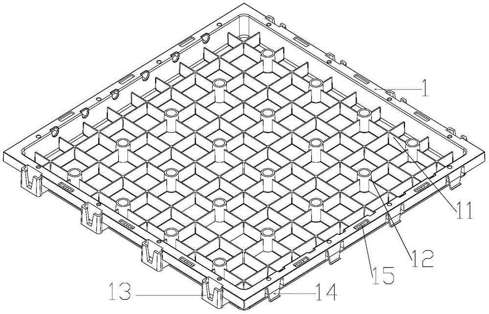
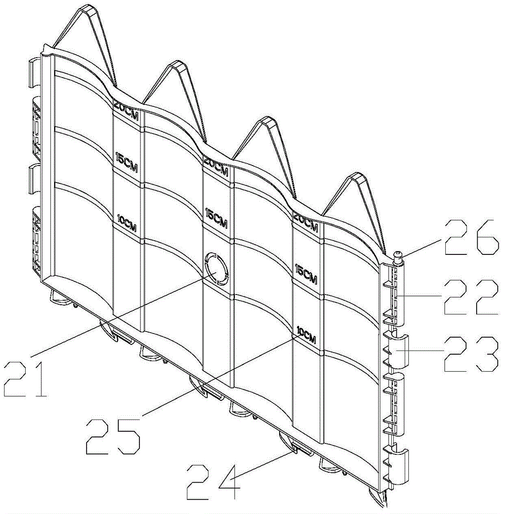
[0029] like figure 1 , 2 As shown, a storage and drainage planting tank includes a bottom plate 1 and a fence 2, the upper edge of the bottom plate 1 is provided with a plug-in groove 15, the plug-in groove 15 is a groove or a through hole structure, and the bottom of the fence 2 is provided with a plug-in slot The socket buckle 24 matched with the groove 15, the fence 2 is plugged on the socket groove of the bottom plate 1 through the socket button 24; The first through hole 12 is set at the intersection of the water grid. In order to make the water storage grid 11 play the role of water storage, the height of the first through hole 12 is not lower than the water storage grid 11, and th...


PUM


Abstract

The invention discloses a planter capable of achieving water storage and drainage. The planter comprises base plates and a fence, wherein insertion grooves are formed in the peripheral edges of the upper end of each base plate, the fence is inserted into the insertion grooves, water storage cells distributed in a latticed mode are arranged on each base plate, first through holes are formed in the positions where the water storage cells distributed in the latticed mode on each base plate intersect, the through holes are not lower than the water storage cells, clamps are arranged on the two lateral sides of each base plate, clamping grooves matched with the clamps are formed in the other two lateral sides of each base plate, and in this way, any two base plates can be clamped together through the clamps and clamping grooves. According to the planter, the base plates, the fence and the connecting rods are all designed to be of splicing structures so that the size of the planter can be adjusted freely as needed; furthermore, the clamping and splicing structures are simple and reliable, the water storage cells and through holes of the base plates can meet the requirements of plants for water storage, water drainage and ventilation, and automatic watering can be achieved. The planter is especially suitable for roofs, balconies, yards, streets and the like.

Description

technical field [0001] The invention relates to the field of plant greening and planting, in particular to a storage and drainage planting tank, which is suitable for roofs, balconies, courtyards, streets and alleys. Background technique [0002] With the advancement of urbanization and increasing food safety issues, more and more urban residents hope to grow flowers and vegetables on their balconies or gardens, and the demand for planting troughs is gradually increasing. The splicing structure of traditional spliced ​​planting tanks is relatively complicated or the splicing is not tight. It is inconvenient to control the amount of watering and fertilization of plants, and it is easy to cause insufficient or excessive waste of water or fertilizer. Corrosion occurs in water environment. For example, a planting box is disclosed in the Chinese patent specification CN20341665U. The bottom of the planting box is provided with a spacer, the upper part of the spacer is provided wi...

Claims


Application Information

Patent Timeline
Patent Type & Authority Patents(China)
IPC IPC(8): A01G9/02A01G27/02
Inventor 宁建强
Owner GUANGDONG WELL TECH
Why Eureka
Try Eureka