Arrangement controlling clearance of sliding bearing

一种滑动轴承、轴承的技术,应用在间隙的装置领域,能够解决冷却系统反应缓慢、消耗大等问题

Active Publication Date: 2014-10-29
SIEMENS GAMESA RENEWABLE ENERGY AS
View PDF8 Cites 10 Cited by
  • Summary
  • Abstract
  • Description
  • Claims
  • Application Information

AI Technical Summary

Problems solved by technology

[0019] The disadvantage of this is that the cooling system reacts slowly to the measured temperature and the cooling system consumes a lot of energy to cool the bearing pads to a certain predetermined temperature

Method used


Image

  • Arrangement controlling clearance of sliding bearing
  • Arrangement controlling clearance of sliding bearing
  • Arrangement controlling clearance of sliding bearing

Examples


Embodiment Construction

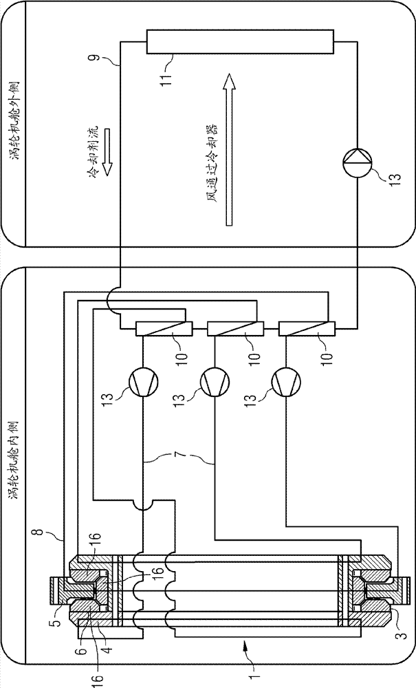
[0127] figure 1 A schematic view of a first embodiment of a bearing arrangement is shown.

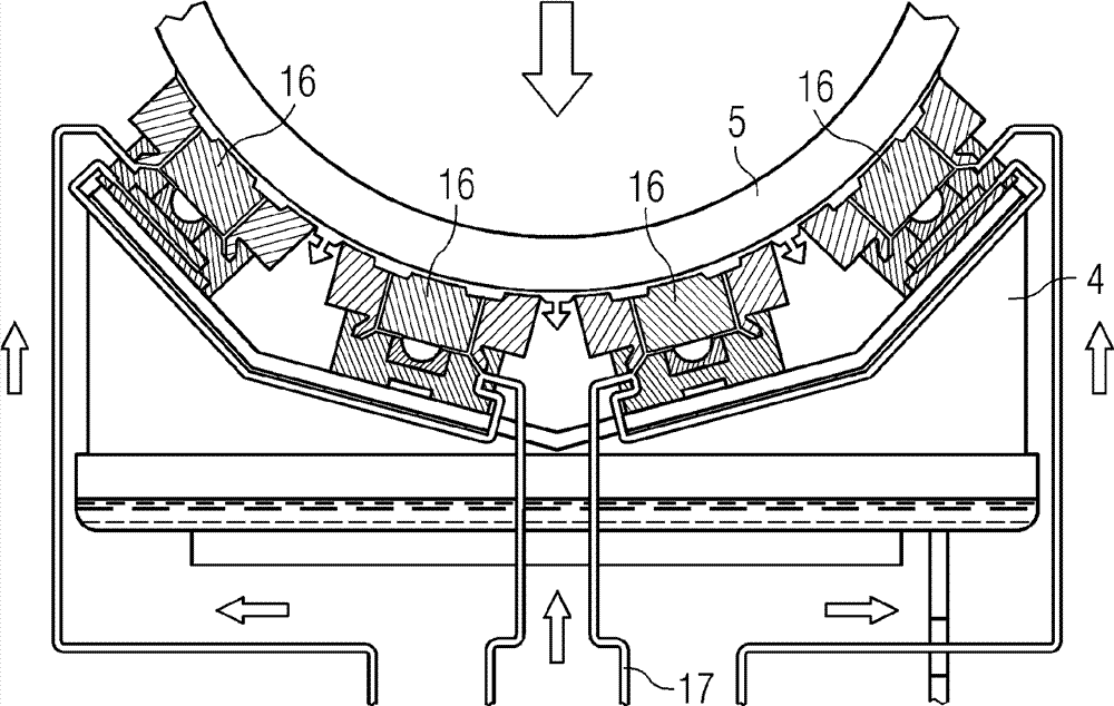
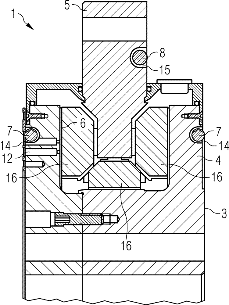
[0128] figure 1 A bearing arrangement 1 comprising bearings is shown. The bearing includes a first bearing shell 4 and a second bearing shell 5 . Bearing pads 16 are attached to the second bearing shell 5 . During operation of the bearing, the bearing pads 16 slide along the surface of the first bearing shell 4 .

[0129] A certain gap 6 is provided between the first bearing shell 4 and the second bearing shell 5 . The gap 6 has to be kept within certain limits in order to avoid damage eg at bearings or the wind turbine.

[0130] The first circuit 7 is arranged on the first bearing shell 4 . The first circuit 7 comprises a first fluid. The first circuit 7 is in thermal contact with the first bearing pad 4 so as to enable the transfer of thermal energy, eg heat, between the first bearing pad 4 and the first fluid. Thus, the first bearing shell 4 can be cooled or heated by the fir...


PUM


Abstract

A sliding bearing arrangement 1, of a direct driven wind turbine 2, comprises a bearing 3 having a first bearing shell 4 and a second bearing shell 5, rotatable with respect to each other. A predetermined clearance 6 is present between the first bearing shell 4 and the second bearing shell 5, while the bearing 3 is in rotation. A first circuit 7 comprising a first fluid is in thermal contact with the first bearing shell 4. A second circuit 8 comprising a second fluid is in thermal contact with the second bearing shell 5. The first circuit 7 and the second circuit 8 are coupled in a way that a difference in the temperature between the first bearing shell 4 and the second bearing shell 5 is compensated via the first and the second fluid, thus the clearance 6 is kept within a predetermined range.

Description

technical field [0001] The invention relates to a device for controlling the clearance of a sliding bearing. Background technique [0002] The bearings are constructed as rolling element bearings or as sliding element bearings. Sliding body bearings or slide bearings are also known as hydrodynamic bearings, hydrostatic bearings or hybrid hydrodynamic and hydrostatic bearings. [0003] The contact surface between rolling elements and bearing pads is very small. In installations where higher loads act on the bearing and greater moments have to be transmitted on the bearing, rolling element bearings are not adequate. [0004] In such devices, sliding body bearings are used. Plain bearings, or plain bearings, are capable of transferring higher loads than rolling element bearings. [0005] In a direct drive wind turbine, the rotor of the generator is directly coupled with the rotor of the wind turbine. The stator of the generator is attached to the stationary part of the win...

Claims


Application Information

Patent Timeline
Patent Type & Authority Applications(China)
IPC IPC(8): F16C25/02F16C41/00F03D11/00
CPCF16C37/00F16C17/243F03D80/70F16C2360/31F16C41/02F16C17/10F16C32/0666F16C32/067F16C32/0696Y10S384/90Y02E10/72
Inventor B.佩德森K.托姆森
Owner SIEMENS GAMESA RENEWABLE ENERGY AS
Why Eureka
Try Eureka