Bridge expansion joint jumping impact test device

A test device, expansion joint technology, applied in the direction of measuring device, force/torque/work measuring instrument, instrument, etc., to achieve the effect of simple structure, accurate and reliable test results

Inactive Publication Date: 2016-04-27
NINGBO UNIV
View PDF3 Cites 0 Cited by
  • Summary
  • Abstract
  • Description
  • Claims
  • Application Information

AI Technical Summary

Problems solved by technology

In the current bridge code, there is no theoretical calculation method and experimental test method for the wheel dynamic load acting on the expansion joint.

Method used


Image

  • Bridge expansion joint jumping impact test device
  • Bridge expansion joint jumping impact test device
  • Bridge expansion joint jumping impact test device

Examples


Embodiment Construction

[0021] The present invention will be further described in detail below in conjunction with the accompanying drawings and embodiments.

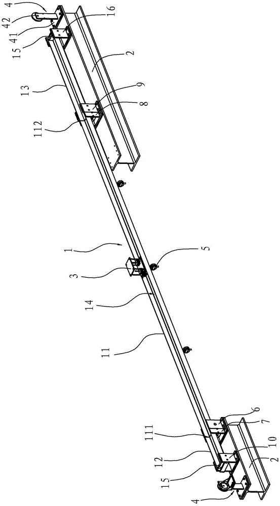
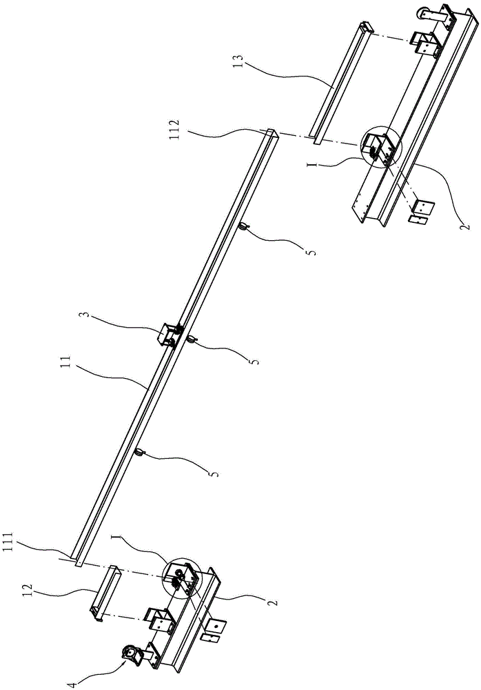
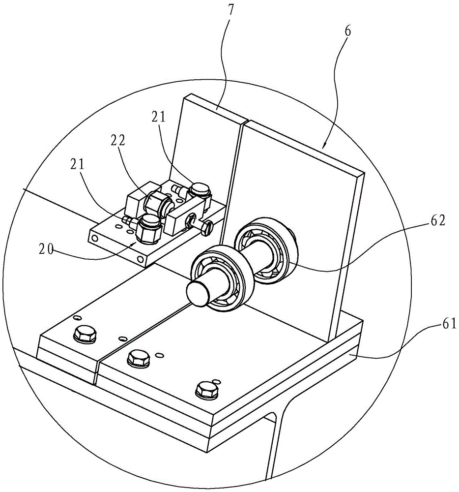
[0022] As shown in claims 1 to 5, the bridge expansion joint vehicle jumping impact test device includes the base 2, the main bridge 11 in the bridge model 1, the approach bridge, the trolley 3 and the sensor group 20, wherein the two ends of the main bridge 11 are respectively One end 111 and the second end 112, the approach bridge comprises the first approach bridge 12 and the second approach bridge 13 and is respectively arranged on the first end portion 111 and the second end portion 112 of the main bridge 11, namely the first approach bridge 12 and the first approach bridge 13. An expansion joint structure is formed between the end portions 111 and an expansion joint structure is formed between the second approach bridge 13 and the second end portion 112 , and the approach bridge and the upper part of the main bridge 11 form a straight bri...


PUM


Abstract

A bridge expansion joint bump impact testing device comprises a base, a bridge model, a trolley and a sensor group. The bridge model is arranged on the base and comprises a main bridge, a first approach bridge and a second approach bridge. The first approach bridge and the second approach bridge are arranged at two ends of the main bridge, two ends of the main bridge are connected with a rolling support and a base through hinged supports respectively, a straightway bridge floor is formed on the first approach bridge, the second approach bridge and the upper portion of the main axle, and the trolley is arranged on the bridge floor and can run on the bridge floor at certain speed. The sensor group comprises a first sensor used for measuring the impact perpendicular to the bridge floor direction and a second sensor used for measuring the impact parallel to the bridge floor direction, and the first sensor and the second sensor are arranged at the connection joints of the main bridge and the first approach bridge and the second approach bridge. Compared with the prior art, the testing device is simple in structure, capable of effectively simulating impact on the bridge expansion joint structure when an automobile runs on and off the bridge and capable of accurately testing impact and provides theoretical basis for high performance bridge expansion joint design, construction and maintenance.

Description

technical field [0001] The invention relates to the fields of civil engineering and traffic engineering, in particular to a device for testing the impact force of vehicle jumping at bridge expansion joints. Background technique [0002] Under the action of temperature and other factors, the bridge will expand and contract longitudinally. In order to meet this deformation, expansion joints need to be set between the ends of the two girders or between the ends of the girder and the abutment. Since the expansion joints bear the dynamic load of the vehicle for a long time, the expansion joints are the weak part of the bridge structure and the main damage location on the current bridge, and the dynamic load of the vehicle wheels is the key parameter for the design, construction and maintenance of the expansion joints. In the current bridge code, there is no theoretical calculation method and experimental test method for the wheel dynamic load acting on the expansion joint. Since...

Claims


Application Information

Patent Timeline
Patent Type & Authority Patents(China)
IPC IPC(8): G01L5/00
Inventor 丁勇林云
Owner NINGBO UNIV
Why Eureka
Try Eureka