A DC circuit breaker magnetic blowing device

A DC circuit breaker, magnetic blowing technology, applied in the direction of circuit breaker parts, circuits, electrical components, etc., can solve the problems of circuit breaker failure, low magnetic permeability, reducing the environmental applicability of the device, safety and reliability, etc., to achieve High safety and reliability, and the effect of improving breaking capacity

Active Publication Date: 2016-08-24
中国船舶重工集团公司第七一二研究所
View PDF10 Cites 3 Cited by
  • Summary
  • Abstract
  • Description
  • Claims
  • Application Information

AI Technical Summary

Problems solved by technology

This method needs to increase the main circuit current detection and judgment device, which makes the magnetic blowing device complicated and reduces the environmental applicability and safety reliability of the device
The permanent magnet blowing device disclosed in patent CN102592910B does not need an external power supply, but still needs a detection and judgment device for the main circuit current, so its environmental applicability and safety reliability are not high
The solution of patent CN102592909B is: use the main circuit current to flow through the magnetic blowing coil to generate the arc blowing magnetic field. This method does not need the main circuit current detection and judgment device, and the structure is relatively simple, but because the magnetic permeability around the magnetic blowing coil is extremely low The blowing arc magnetic field generated by the magnetic blowing coil will decrease sharply with the increase of the distance from the coil. In addition, this method only reaches the upper end of the magnetic blowing coil when the arc root reaches the upper end of the magnetic blowing coil, that is, the current must flow through the magnetic blowing coil. The blowing magnetic field will be generated, so when the arc does not reach the magnetic blowing coil, the magnetic blowing device will not work. If the arc cannot move to the magnetic blowing coil under the action of the main circuit magnetic field at this time, the circuit breaker will break fail

Method used


Image

  • A DC circuit breaker magnetic blowing device
  • A DC circuit breaker magnetic blowing device
  • A DC circuit breaker magnetic blowing device

Examples


Embodiment 1

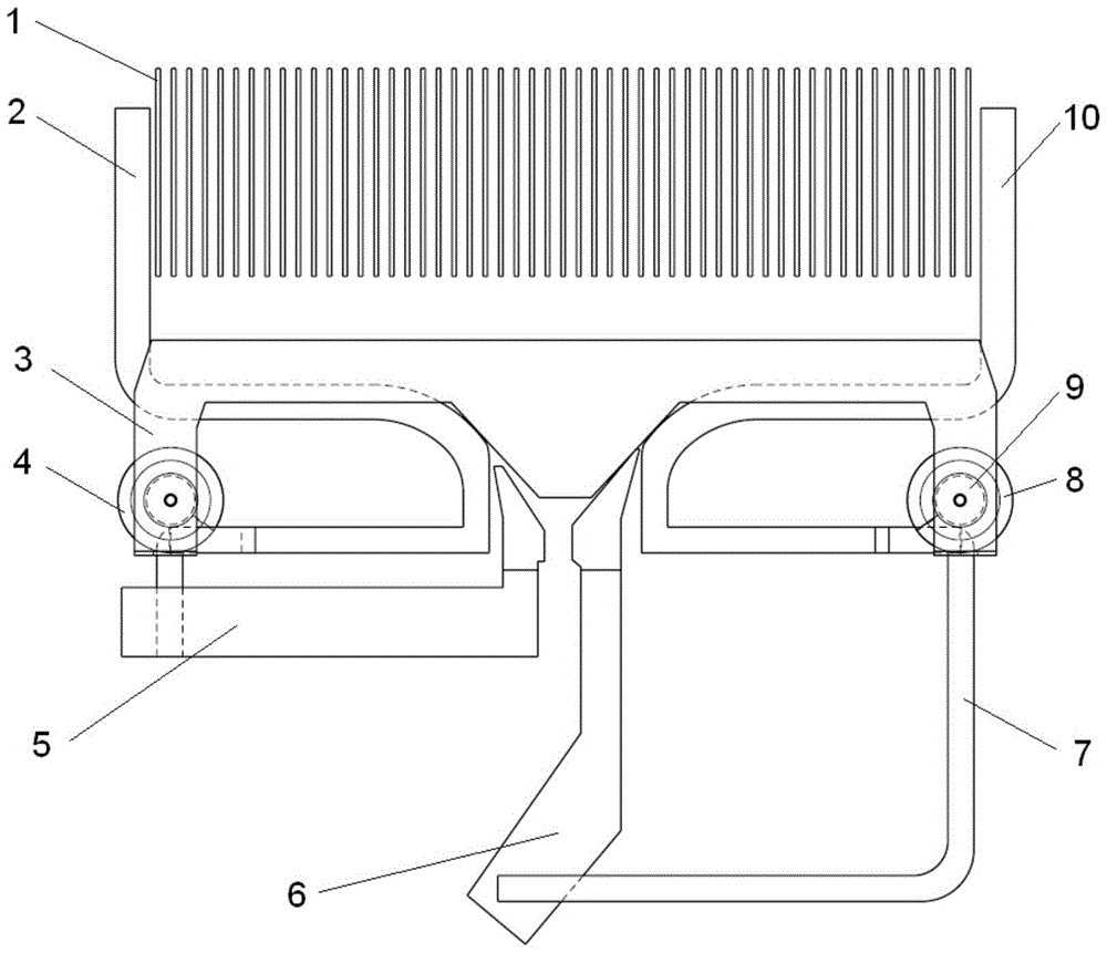
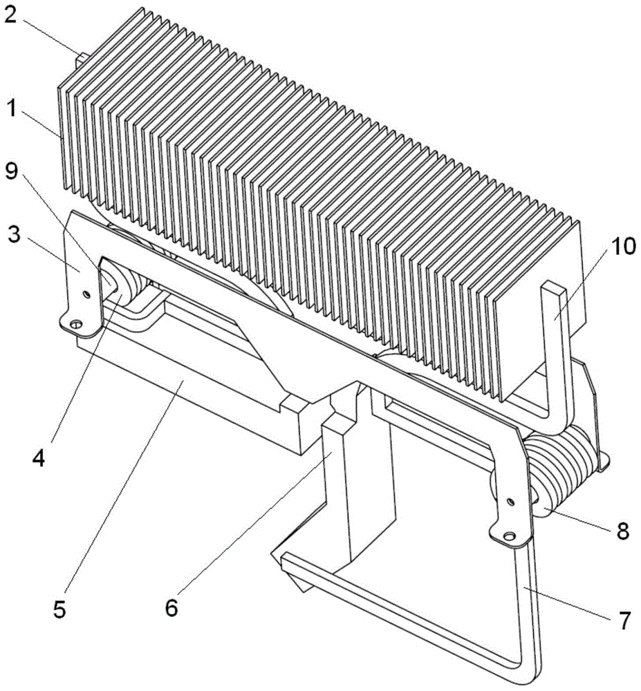
[0025] 1. First, introduce the structure of the present invention. A DC circuit breaker magnetic blowing device of the present invention includes a static end arc striking angle 2 and a moving end arc striking angle 10 arranged at both ends of the arc extinguishing chamber 1; two symmetrically arranged guide magnets The plate 3 is located between the arc striking angle 2 of the static end and the arc striking angle 10 of the moving end, and is arranged under the arc extinguishing chamber; a magnetic blowing coil 4 of the static end is respectively connected with the arc striking angle 2 of the static end and the static contact 5 at both ends , the inner cavity of the static end magnetic blowing coil 4 is coaxially placed with an iron core 9; a moving end magnetic blowing coil 8 connected to the moving end arc striking angle 10 and the moving contact through a wire 7 at both ends, the described An iron core 9 is coaxially placed in the inner cavity of the magnetic blowing coil 8...

Embodiment 2

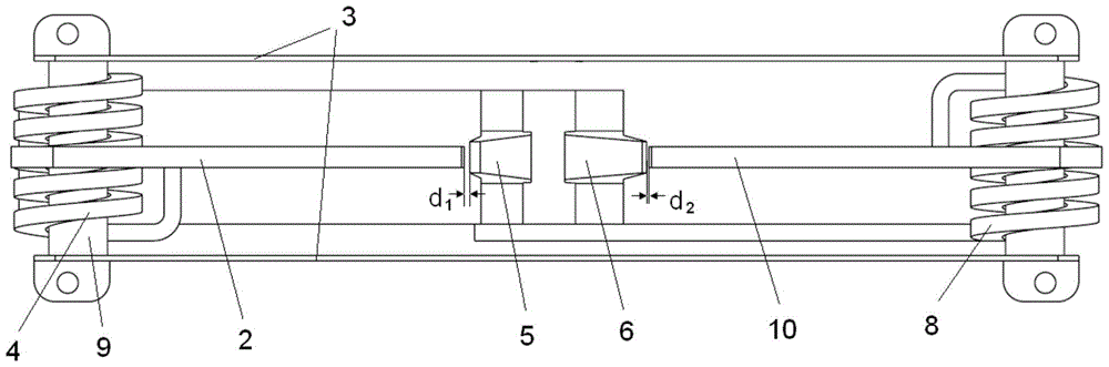
[0029] Example 2: Figure 1~3 The magnetic guide plate 3 in can also be Figure 6 In the structure shown, the structure is to separate the magnet-conducting plate 3 from the symmetrical plane in the middle, and keep a certain distance therebetween. Other structures are the same as in Embodiment 1, and will not be repeated here.

[0030] When working, when the arc is transferred to the dynamic (static) end arc ignition angle 10 (2), the arc will connect the dynamic (static) end arc ignition angle 10 (2) and the dynamic (static) end magnetic blowing coil 8 (4) in series Together, according to Ampere's law, it can be seen that the iron core 9 installed in the cavity of the dynamic (static) end magnetic blowing coil 8 (4) will induce a magnetic field, due to the winding of the static end magnetic blowing coil 4 and the moving end magnetic blowing coil 8 Therefore, the direction of the induced magnetic field in the iron core 9 is the same, and the winding direction of the magne...


PUM


Abstract

The invention relates to a magnetic blowing device for a DC circuit breaker, which includes a static end arc striking angle, a magnet plate, a static end magnetic blowing coil, a static contact, a moving contact, a wire, a moving end magnetic blowing coil, an iron core, and a moving end arc angle. An iron core is coaxially placed in the magnetic blowing coil at the static end, and its two ends are respectively connected with the arc striking angle and the static contact at the static end; an iron core is placed coaxially in the magnetic blowing coil at the moving end, and its two ends are connected with the The end arc angle and the connection with the moving contact through the wire; the two ends of the magnet plate are closely matched with the same side end faces of the two iron cores; the axial end faces of the static end magnetic blowing coil and the moving end magnetic blowing coil do not exceed the iron core same-side end face. Advantages: 1. The direction of the arc blowing magnetic field can automatically change with the change of the main circuit current, so the safety and reliability are high; 2. The arc blowing magnetic field is concentrated in the fracture area of ​​the dynamic and static contacts and the area near the arc strike angle, which is effective It is conducive to the rapid movement of the arc root, thereby driving the arc to quickly enter the arc extinguishing chamber, and improving the breaking capacity of the circuit breaker.

Description

technical field [0001] The invention relates to a magnetic blowing device, in particular to a magnetic blowing device for a DC circuit breaker. Background technique [0002] During the breaking process of the air circuit breaker, an arc will be generated between the moving and static contacts, and the arc and the conductive circuit of the contact will generate an arc blowing magnetic field that is beneficial for the arc to enter the arc extinguishing chamber. The arc will be affected by the arc blowing magnetic field. The action of the electric power of the circuit enters the arc extinguishing chamber. This method of using the electromotive force generated by the main circuit itself to drive the arc into the arc extinguishing chamber to extinguish the arc is called the self-excitation excitation method. The power becomes smaller and not enough to drive the arc into the arc extinguishing chamber, the arc will stagnate at the arc ignition angle and continue to burn, causing t...

Claims


Application Information

Patent Timeline
Patent Type & Authority Patents(China)
IPC IPC(8): H01H73/18H01H9/44
Inventor 马子文肖文华赵成宏涂煜赵喜军
Owner 中国船舶重工集团公司第七一二研究所
Why Eureka
Try Eureka