
Center of gravity position detection device, center of gravity position detection method and program

A center of gravity position, detection device technology, applied in the direction of measuring devices, storage devices, transportation and packaging, etc., can solve the problem that the container is easy to lose balance

Active Publication Date: 2014-11-05
SUMITOMO HEAVY IND MATERIAL HANDLING SYST
View PDF9 Cites 14 Cited by
  • Summary
  • Abstract
  • Description
  • Claims
  • Application Information

AI Technical Summary

Problems solved by technology

That is, when the center of gravity of the container is high, it is more likely to lose balance than when the center of gravity is low

Method used


Image

  • Center of gravity position detection device, center of gravity position detection method and program
  • Center of gravity position detection device, center of gravity position detection method and program
  • Center of gravity position detection device, center of gravity position detection method and program

Examples


no. 1 Embodiment approach >

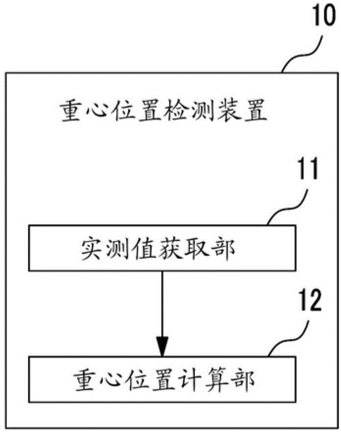
[0033] figure 1 It is a schematic block diagram showing the functional configuration of the center-of-gravity position detection device in the first embodiment of the present invention. In this figure, the center-of-gravity position detection device 10 includes an actual value acquisition unit 11 and a center-of-gravity position calculation unit 12 . The actual measurement value acquisition part 11 acquires the actual measurement value of the data which shows the suspension state of an hanging load, and this actual measurement value is an actual measurement value acquired in at least 2 different states.

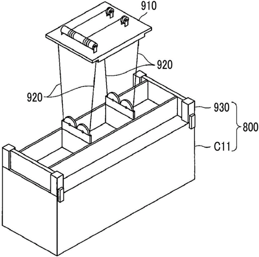
[0034] here, figure 2 It is explanatory drawing which shows the example of the hanging load which the center-of-gravity position detection apparatus 10 makes into the object of center-of-gravity position detection. This figure shows a trolley 910 with a crane, a rope 920, a box frame 930, and a container C11. The container C11 is held by the hanging box frame 930 and lift...

no. 2 Embodiment approach >

[0048] In the second embodiment, an example in which the center-of-gravity position detection device 10 described in the first embodiment is further embodied will be described.

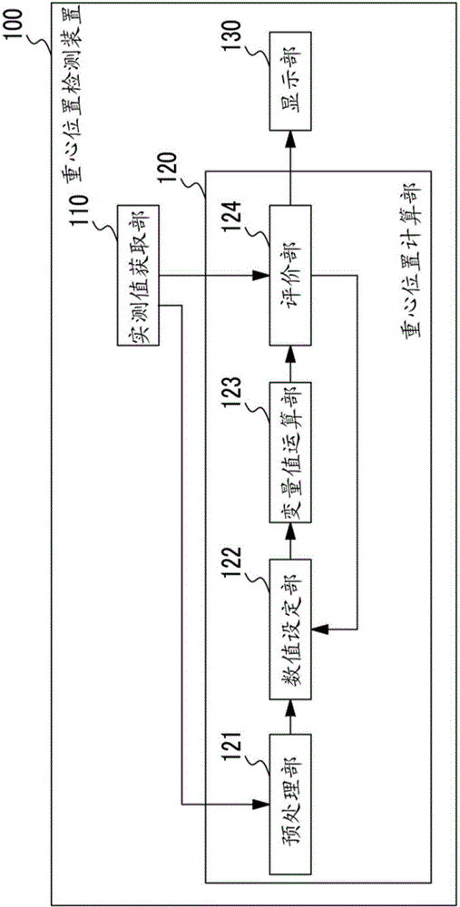
[0049] image 3 It is a schematic block diagram showing the functional configuration of the center-of-gravity position detection device in the second embodiment of the present invention. In this figure, the center-of-gravity position detection device 100 includes an actual value acquisition unit 110 , a center-of-gravity position calculation unit 120 , and a display unit 130 . The center-of-gravity calculation unit 120 includes a preprocessing unit 121 , a numerical value setting unit 122 , a variable value calculation unit 123 , and an evaluation unit 124 .

[0050] The measured value acquisition unit 110 corresponds to the measured value acquisition unit 11 ( figure 1 In an example of ), the actually measured value of the data showing the state of the suspended load is acquired from the time-serie...

no. 3 Embodiment approach >

[0166] In the third embodiment, another example in which the center-of-gravity position detection device 10 described in the first embodiment is further embodied will be described.

[0167] The functional structure of the center of gravity position detection device in this embodiment and figure 1 The structure shown is the same, the following reference figure 1 Be explained. However, in this embodiment, the actual measurement value acquisition part 11 acquires the suspension state actual measurement value in the static state of an hanging load.

[0168] In particular, the actual measurement value acquisition part 11 acquires the actual measurement value of the data which shows the hanging state of an hanging load including the actual measurement value of the rotation amount (rotation angle) of an hanging load, and the actual measurement value of the hanging load position.

[0169] And the center-of-gravity position calculation part 12 uses the static model of an hanging load...


PUM


Abstract

This center of gravity position detection device calculates the center of gravity position of a suspended load suspended by a rope, and is provided with a measured value acquisition unit which, for at least two different states, acquires measured values from data indicating the state in which the suspended load is suspended, and a center of gravity position calculation unit which calculates the center of gravity position of the suspended load on the basis of a state model of the suspended load which includes at least the center of gravity position of the suspended load as an unknown variable and the measured values acquired by the measured value acquisition unit.

Description

technical field [0001] The invention relates to a gravity center position detection device, a gravity center position detection method and a program. [0002] This application claims priority based on Patent Application No. 2012-234945 for which it applied in Japan on October 24, 2012, and uses the content here. Background technique [0003] In order to prevent a container transport vehicle or the like from losing balance during transport of the container, it is effective to detect the position of the center of gravity in the height direction (up and down direction) of the container. That is, when the position of the center of gravity of the container is high, it is easy to lose balance compared to when the position of the center of gravity is low. Therefore, when the position of the center of gravity of the container is high, measures such as rearranging the contents of the container to lower the position of the center of gravity or calling attention to the driver of the c...

Claims


Application Information

Patent Timeline
IPC IPC(8): G01M1/12B65G63/00G01G19/14
CPCB66C13/08B66C13/16B65G63/00G01G19/14G01M1/12G01M1/122
Inventor 柳井法贵门前唯明林大作
Owner SUMITOMO HEAVY IND MATERIAL HANDLING SYST
Learn More