
Light-gathering device for high-speed camera micrograph of nozzle spray pattern

A high-speed camera, nozzle spray technology, applied in high-speed photography, condenser lens, optics, etc., can solve the problems of reduced light quantity, higher requirements for light, affecting the effect of light gathering, etc., to enhance adaptability, maintain stability, ensure cleaning effect

Inactive Publication Date: 2016-08-17
TIANJIN UNIV
View PDF6 Cites 0 Cited by
  • Summary
  • Abstract
  • Description
  • Claims
  • Application Information

AI Technical Summary

Problems solved by technology

[0002] In the high-speed camera research of engine fuel injector spray, the shooting speed reaches tens of thousands or even hundreds of thousands of frames per second, which requires sufficient light intensity to ensure the clarity of the captured pictures, especially when using a microscope to observe the opening of the fuel injector. , When the local spray characteristics of the nozzle holes are closed, it is difficult to meet the light intensity requirements of high-speed shooting by directly using a strong light source. In addition, the vibration of the fuel injection will affect the light focusing effect. high demands
Some scholars have proposed to use a convex lens to concentrate light on the light source. This method can improve the brightness of the captured pictures to a certain extent, but it often cannot meet the requirements when shooting at higher speeds.
The nozzle holes of direct injection gasoline engine injectors and high pressure common rail diesel engine injectors are generally arranged on non-planar conical surfaces. Because of the existence of the cone angle, the amount of reflected light entering the high-speed camera lens will be reduced, thereby affecting Clarity of shooting
Especially after the microscope lens is installed, the effective observation area is very small, and the requirements for light are higher. Just using the light source surface lighting method can no longer meet the needs of further research.

Method used


Image

  • Light-gathering device for high-speed camera micrograph of nozzle spray pattern
  • Light-gathering device for high-speed camera micrograph of nozzle spray pattern
  • Light-gathering device for high-speed camera micrograph of nozzle spray pattern

Examples


Embodiment

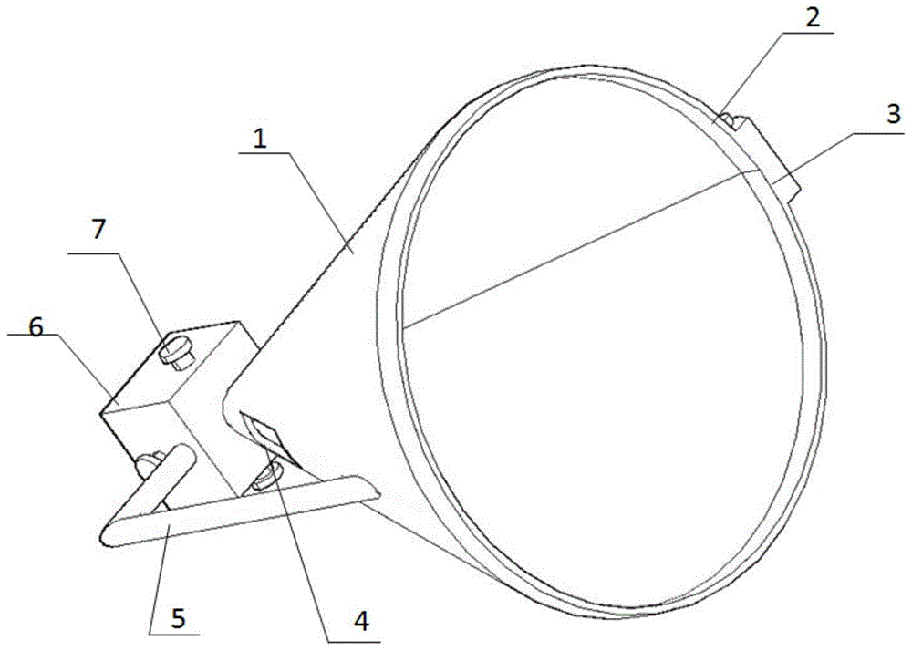
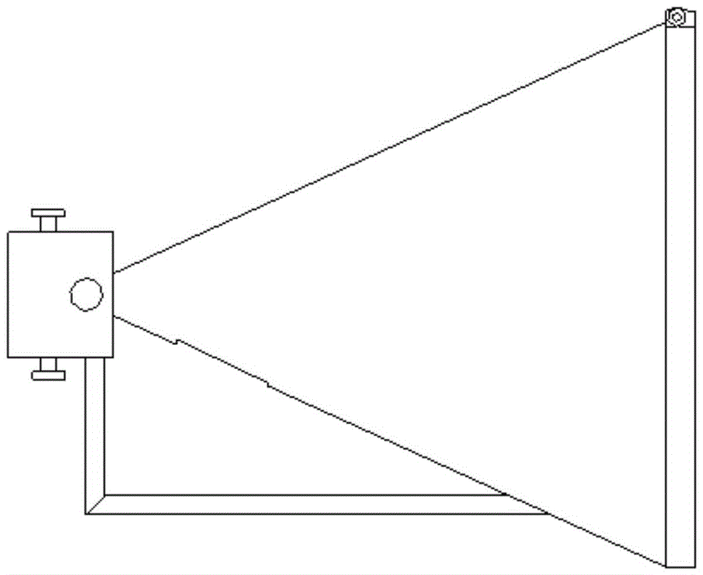
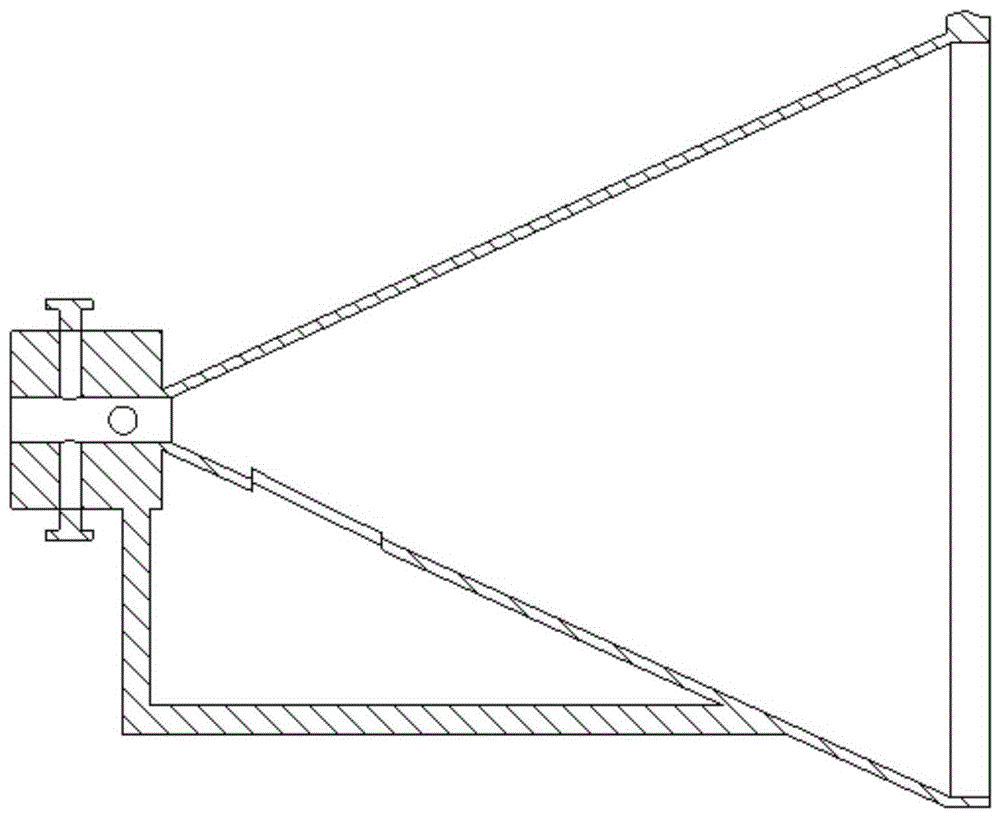
[0026] Concentrating device for high-speed camera microscopic photography of nozzle spray patterns, including:

[0027] The conical condenser 1 has a first through hole along the cone centerline direction at the top of the cone; the fixture 6 connected to the cone top of the conical condenser has a through hole in the fixture, and the nozzle passes through the through hole 11, the first A through hole is located in the conical condenser; the conical condenser is connected to the fixing device through the fixing frame 5;

[0028] The conical condenser is rolled from a piece of flexible fan-shaped reflector; and also includes: an adjustable clamp 3 positioned at the outer peripheral surface of the cone bottom of the conical condenser, by rotating the knob 2, the adjustable clamp can be tightened and tightened. Relax, and then adjust the cone angle of the cone condenser.

[0029] The range of the adjustable clamp to adjust the cone angle of the conical surface condenser is great...


PUM


Abstract

The invention mainly relates to the technology of an engine fuel injector, and further relates to a light concentrating device for enhancing the brightness of a fuel injector nozzle when a high-speed camera microscopically photographs the spray form of the fuel injector. The concentrating device used for high-speed camera microscopic shooting nozzle spray form, including: conical concentrating lens 1, a fixing device 6 connected to the cone top of the conical concentrating mirror; . Compared with the prior art, the beneficial effect of the present invention is: through the reflection of the converging cone surface, it is ensured that after the strong light source irradiates the nozzle, as much reflected light as possible enters the microlens of the high-speed camera, effectively ensuring that the tiny area enters the lens. The amount of light entering.

Description

Technical field: [0001] The invention mainly relates to the technology of an engine fuel injector, and further relates to a light concentrating device for enhancing the brightness of a fuel injector nozzle when a high-speed camera microscopically photographs the spray form of the fuel injector. Background technique: [0002] In the high-speed camera research of engine fuel injector spray, the shooting speed reaches tens of thousands or even hundreds of thousands of frames per second, which requires sufficient light intensity to ensure the clarity of the captured pictures, especially when using a microscope to observe the opening of the fuel injector. , When the local spray characteristics of the nozzle holes are closed, it is difficult to meet the light intensity requirements of high-speed shooting by directly using a strong light source. In addition, the vibration of the fuel injection will affect the light focusing effect. high demands. Some scholars have proposed to use ...

Claims


Application Information

Patent Timeline
Patent Type & Authority Patents(China)
IPC IPC(8): G03B39/00G03B15/02G02B19/00
Inventor 姚春德窦站成耿培林银增辉陈志方
Owner TIANJIN UNIV
Learn More