
Supporting frame

A technology of support frame and support part, applied in the field of support frame, can solve the problem of inability to stop the cart and the like

Inactive Publication Date: 2014-11-19
兴锋脚轮(江苏)有限公司
View PDF6 Cites 2 Cited by
  • Summary
  • Abstract
  • Description
  • Claims
  • Application Information

AI Technical Summary

Problems solved by technology

[0002] At present, the existing universal roller carts can only be parked on flat ground, and cannot stop the carts when encountering slopes. Device for parking cars on slopes

Method used


Image

  • Supporting frame
  • Supporting frame

Examples


Embodiment 1

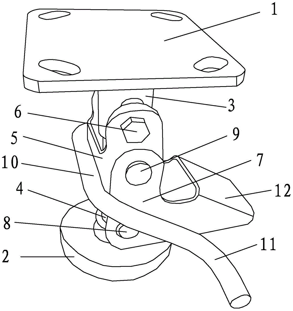
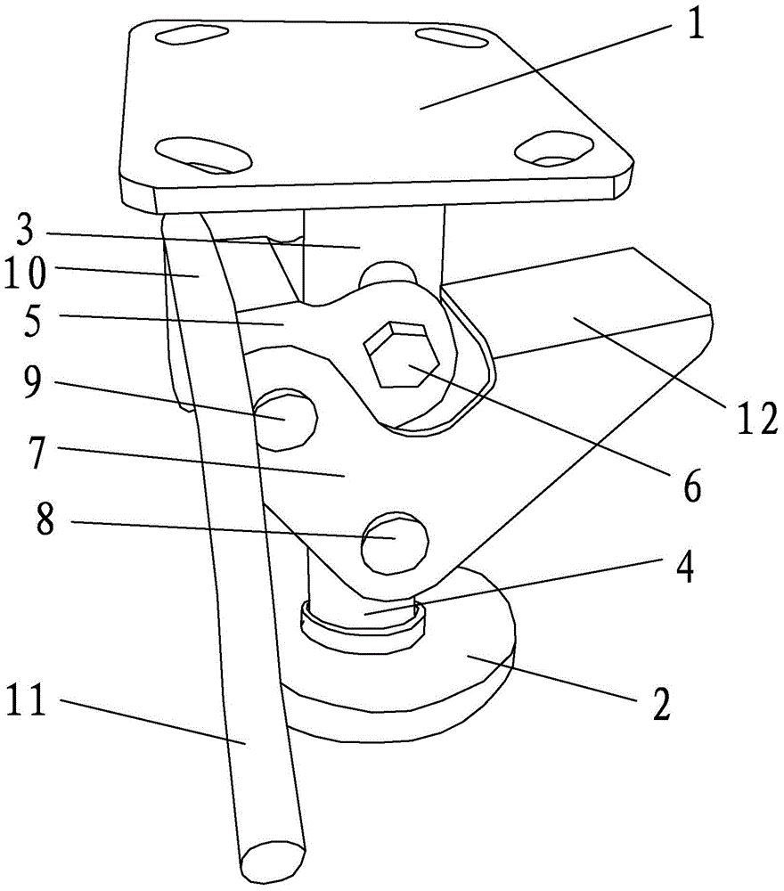
[0014] Embodiment one: see attached Figure 1-2 As shown, a support frame includes an upper support part 1 and a lower support part 2. The middle part of the upper support part 1 has a hollow tubular sliding sleeve 3 extending downward, and the middle part of the lower support part 2 has a hollow support extending upward. The column 4 and the support column 4 are movably clamped in the sliding sleeve 3, and the upper part of the sliding sleeve 3 is radially penetrated with a first shaft 6, and the two ends of the first shaft 6 are rotatably connected with the first rotating block 5, and the first rotating block 5 is U-shaped and its two ends are respectively connected to the first shaft 6 in rotation. The lower part of the support column 4 is provided with a second shaft 8 in the radial direction. The two ends of the second shaft 8 are rotatably provided with a second rotating block 7. The first shaft 6 is arranged parallel to the second shaft 8, the first rotating block 5 i...


PUM


Abstract

The invention discloses a supporting frame. The supporting frame comprises an upper supporting part and a lower supporting part. The middle of the upper supporting part is provided with a hollow tubular sliding sleeve extending downwards, the middle of the lower supporting part is provided with a hollow supporting column extending upwards, the upper portion of the sliding sleeve is radially provided with a first shaft in a penetrating mode, the two ends of the first shaft are rotationally connected with first rotating blocks, the lower portion of the supporting column is radially provided with a second shaft in a penetrating mode, and the two ends of the second shaft are rotationally provided with second rotating blocks. A treading part is pressed to drive the first rotating blocks and the second rotating blocks to rotate, the supporting frame can be supported and kept in a self-locking state, after a handle is pressed, the first rotating blocks and the second rotating blocks are reset through elastic force of a tension spring, and the supporting frame is collected.

Description

technical field [0001] The invention relates to the field of universal roller carts, in particular to a support frame. Background technique [0002] At present, the existing universal roller carts can only park on flat ground, and cannot stop the carts when encountering slopes. Therefore, a device that can park the carts on slopes is needed at present. Contents of the invention [0003] The purpose of the present invention is to provide a support frame that can be stretched up and down. [0004] In order to achieve the above object, the technical solution adopted by the present invention is: a support frame, which includes an upper support part and a lower support part, the middle part of the upper support part has a hollow tubular sliding sleeve extending downward, and the lower support part The middle part has a support column extending upwards, and the support column is movably clamped in the sliding sleeve. The upper part of the sliding sleeve is provided with ...

Claims


Application Information

Patent Timeline
Patent Type & Authority Applications(China)
IPC IPC(8): B62B5/00B62B5/06
Inventor 顾兴锋
Owner 兴锋脚轮(江苏)有限公司
Learn More