
Self-locking battery module

A battery module, self-locking technology, applied in battery pack parts, circuits, electrical components, etc., can solve the problem of shell welding, poor structural integrity of the cell and module bracket, and high stamping cost. The thickness of the busbar material and other problems to achieve the effect of increasing life, achieving reliability and structural stability, and excellent quality

Pending Publication Date: 2020-11-06
JIAXING MODULE BONDING TECH CO LTD +1
View PDF0 Cites 3 Cited by
  • Summary
  • Abstract
  • Description
  • Claims
  • Application Information

AI Technical Summary

Problems solved by technology

Due to the problems of shell penetration, virtual welding, false welding, and poor structural integrity between the battery cell and the module bracket in the original thermal welding process, the original busbar for module packaging needs to be customized in advance, high stamping cost, busbar material thickness, etc. Restriction is the pain point of the industry

Method used


Image

  • Self-locking battery module
  • Self-locking battery module
  • Self-locking battery module

Examples


Embodiment 1

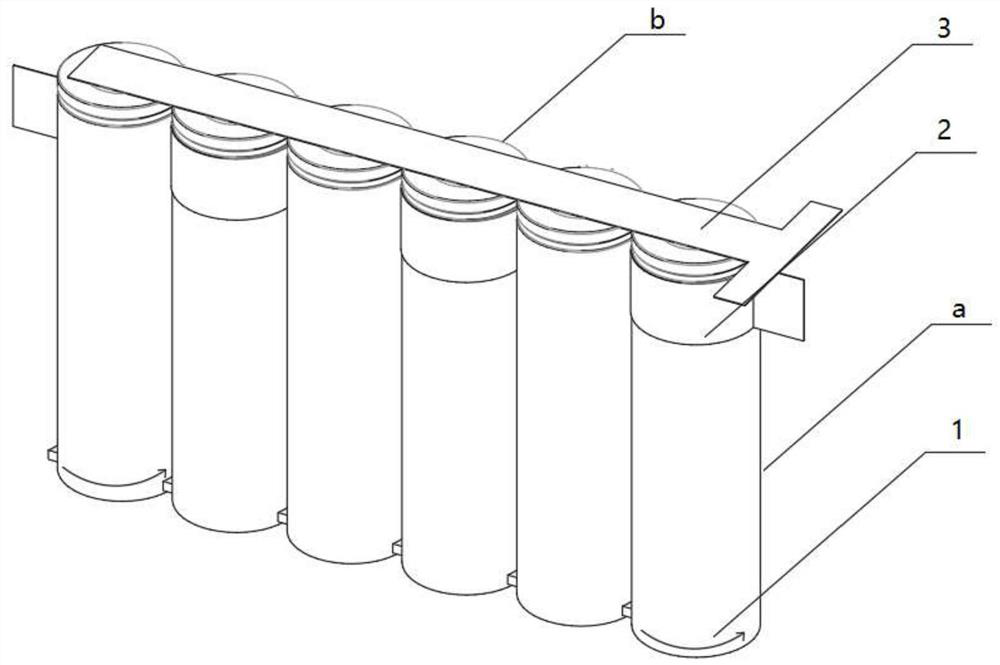
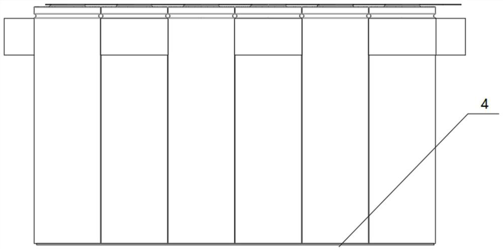
[0030] like figure 1 and figure 2 As shown, taking a battery module with 6 cells as an example, arrange the 6 cells 1 in a row, and weld or glue one end of the pole bus bar 2 to the shell on the side of the cell 1 at the head end. Seal; wrap the 2 rows of poles of the solid-sealed case with an S-shaped structure and wrap the side shells of the remaining rows of cells 1 in turn, and weld the other end of the pole bus 2 of the case to the side shell of the terminal cell 1 Or side sealing; set the center points of the cells 1 arranged in rows on the same X-axis line, and at the same time restrict the cells 1 from being displaced in the direction of the Y-axis, and concatenate the first or end cells 1 along the shell poles The row is fully wound in the direction of the battery cell 1 and rotates. The first and the end cells move closer to each other along a straight line. Tight and electrically reliable cold connections form an integrated structure in which all housing poles ar...

Embodiment 2

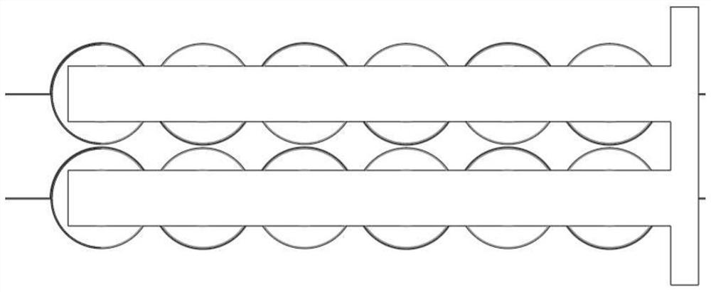
[0033] like image 3 As shown, the adjacent battery modules of the two battery modules in Embodiment 1 are arranged in a matrix or interlaced and complementary, and the adjacent battery modules are respectively connected at the neck and the lower end by solid sealing. Obtained a parallel array battery large module, in which the top poles of the cells in the large module are connected in parallel through the entire top pole bus bar.

Embodiment 3

[0035] like Figure 4 As shown, 6 batteries 1 are arranged in a row, and the self-locking connection is carried out in the middle of the side shell of the batteries in the manner of Example 1. The contact points between adjacent batteries 1 and the standard bus bar 2 are passed through UV Adhesive connection, the opposite surfaces of the lower ends of adjacent battery cells 1 are connected by UV glue.

[0036] The 6 cells 1 are equivalent to two modules consisting of 3 cells 1, the first 3 cells 1 are inverted, the last three cells are inverted, and the top poles of the two modules are sealed with top poles. Column busbar3.


PUM


Abstract

The invention relates to the field of battery module packaging, in particular to a battery module which is arranged in line in rows, has shell poles connected in parallel and is stable in structure. The module comprises a plurality of cylindrical battery cells and busbars, two poles of the battery cells are a top pole and a shell pole; a self-locking mechanism is connected between the shells on the side surfaces of the battery cell; the self-locking mechanism is an S-shaped pole busbar which is wound on shells on the side surfaces of all the battery cells; the battery module is electrically connected with all battery cell side surface shell polar columns of the module to realize parallel connection among all battery cell shell polar columns of the module; the top pole busbar is electrically connected with the top poles of the cells arranged in the same direction of the module to realize parallel connection between the top poles of the cells; and the outer poles of the two poles of themodule are outward extending parts at the two ends of the top pole busbar and the shell pole busbar. The self-locking mechanism adopted by the invention realizes the improvement of the electric connection reliability of the parallel shell polar columns and the stability of the overall structure of the module.

Description

technical field [0001] The invention relates to the field of packaging of battery modules, in particular to a battery module arranged in a row, housing poles connected in parallel, and stable in structure. Background technique [0002] A battery module with high capacity is formed by connecting batteries in parallel, and a high-voltage battery module is formed by connecting batteries in series, which is a common method for packaging energy storage units of electric vehicles. The reliability of the electrical connection between the negative pole of the cylindrical battery and the busbar and the reliability of the overall structure of the parallel module are widely concerned issues in the industry. Due to the problems of shell penetration, virtual welding, false welding, and poor structural integrity between the battery cell and the module bracket in the original thermal welding process, the original busbar for module packaging needs to be customized in advance, high stamping ...

Claims


Application Information

Patent Timeline
IPC IPC(8): H01M2/10H01M2/20
Inventor 汪波杨钢冯栋
Owner JIAXING MODULE BONDING TECH CO LTD
Learn More