Passive LED flash transaction card, preparation method and transaction display method
A transaction card, LED light technology, applied in the recording medium, instruments, computer parts and other directions used by the machine, can solve the problems of no special design, unfavorable promotion and use, etc., to increase the personalized design, facilitate the promotion and use, and improve the use of the effect of interest
- Summary
- Abstract
- Description
- Claims
- Application Information
AI Technical Summary
Problems solved by technology
Method used
Image
Examples
Embodiment 1
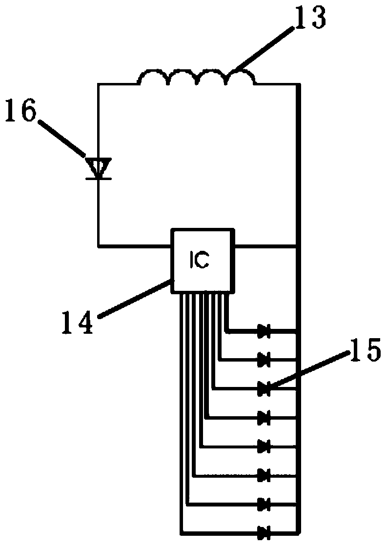
[0029] Such as figure 1 and figure 2 As shown, the passive LED flash transaction card includes a card body 11 and a circuit board 12 disposed in the card body 11. The circuit board 12 is provided with a coil 13 and a control chip 14 connected to each other. The control chip 14 controls and connects a plurality of devices. On the LED lamp 15 on the circuit board 12; the control chip 14 is provided with:
[0030] The database module is used to set multiple transaction modes and multiple control modes corresponding to the multiple transaction modes respectively;
[0031] The identification module is used to identify the transaction mode according to the radio frequency signal of the transaction, and then determine the control mode corresponding to the transaction mode;
[0032] The control module is used for controlling the plurality of LED lamps 15 to perform different displays according to the plurality of control modes.
[0033] The identification method used in identifyin...
Embodiment 2
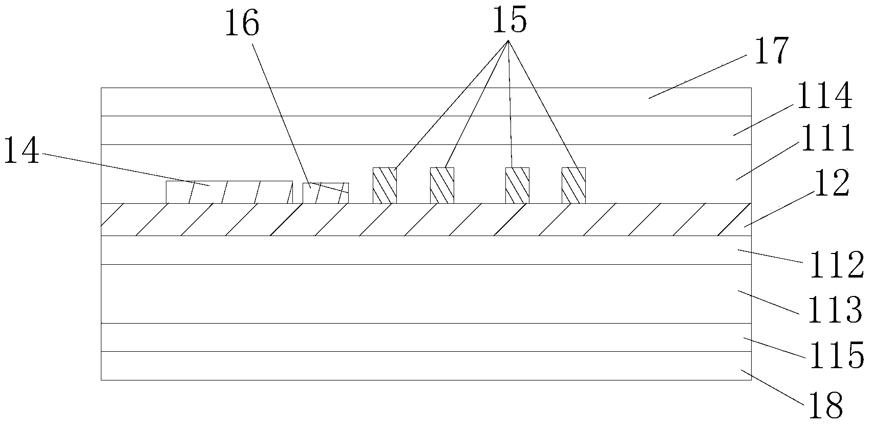
[0044] to combine figure 2 and image 3 As shown, in this embodiment, further specific design is mainly aimed at the passive LED flash transaction card of the first embodiment. In this embodiment, the card body 11 includes a first fixed layer card base 111, a first transparent PVC coating 112, a second fixed layer card base 113, a first printed layer card base 114 and a second printed layer card base 115, the control chip 14, a plurality of LED lamps 15, and rectifier diodes 16 are all located on the same side of the circuit board 12, and the first fixed layer card base 111 is provided with corresponding to the control chip 14, a plurality of LED lamps 15 and rectifier diodes 16 respectively. Placement space, the first printed layer card base 114, the first fixed layer card base 111, the circuit board 12, the first transparent PVC coating 112, the second fixed layer card base 113 and the second printed layer card base 115 in order Arranged and integrated, the control chip 1...
PUM
 Abstract
Description
Claims
Application Information
 - R&D
- Intellectual Property
- Life Sciences
- Materials
- Tech Scout
- Unparalleled Data Quality
- Higher Quality Content
- 60% Fewer Hallucinations
Browse by: Latest US Patents, China's latest patents, Technical Efficacy Thesaurus, Application Domain, Technology Topic, Popular Technical Reports.
© 2025 PatSnap. All rights reserved.Legal|Privacy policy|Modern Slavery Act Transparency Statement|Sitemap|About US| Contact US: help@patsnap.com


