Extremely high temperature resistant and adjustable pneumatic loop sealing valve device

A sealing valve and high-temperature-resistant technology, which is applied in the field of chemical engineering, can solve problems such as difficult to meet production needs, difficult selection of materials and structures, and material surge, so as to save materials, facilitate wire-cut processing, and prevent high-temperature oxidation of tungsten. Effect

Active Publication Date: 2014-12-03
SHENYANG XINBO IND TECH
View PDF4 Cites 2 Cited by
  • Summary
  • Abstract
  • Description
  • Claims
  • Application Information

AI Technical Summary

Problems solved by technology

When the pressure fluctuations on both sides of the valve body of this kind of pneumatic loop sealing valve are large, material gushing phenomenon often occurs, so it is difficult to effectively control the feeding amount and discharging amount, and it is difficult to meet the production needs
In addition, for valves that work in a high-temperature aerobic atmosphere above 1400 °C, the selection of materials and structures is also a major problem at present.
Because it has not yet found a material that can withstand extremely high temperature oxidation above 1400°C, has extremely high temperature strength and wear resistance without brittleness, and a loop seal valve made of it

Method used


Image

  • Extremely high temperature resistant and adjustable pneumatic loop sealing valve device
  • Extremely high temperature resistant and adjustable pneumatic loop sealing valve device
  • Extremely high temperature resistant and adjustable pneumatic loop sealing valve device

Examples


Embodiment Construction

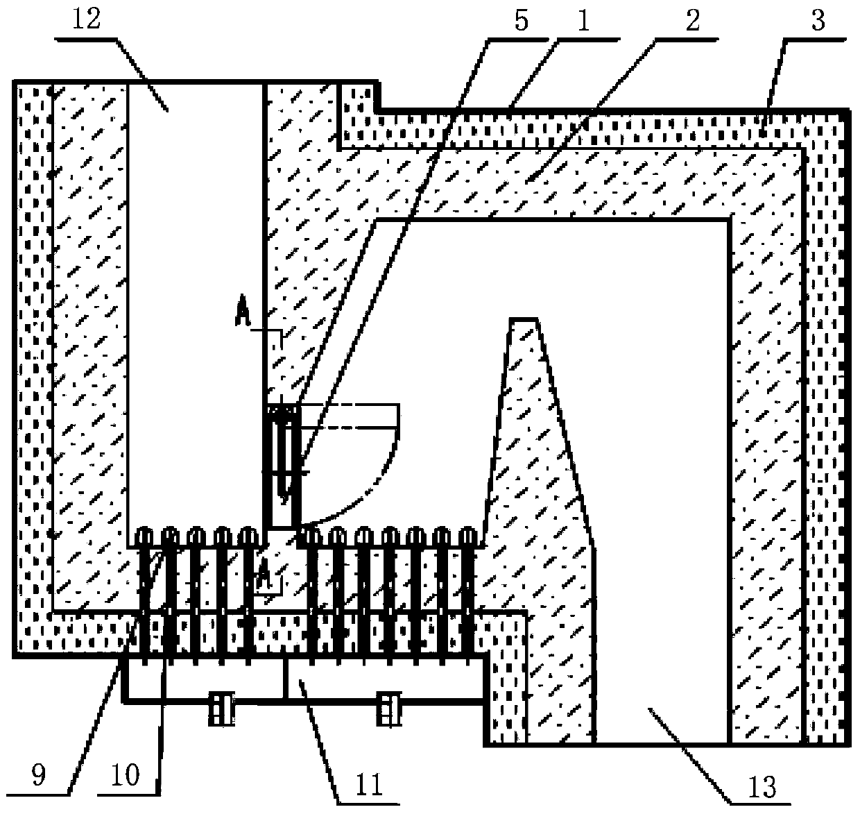
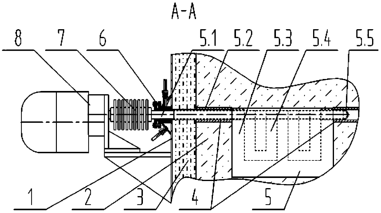
[0023] The present invention will be further described in detail below in conjunction with the accompanying drawings and specific embodiments.

[0024] like figure 1 , figure 2 As shown, an extremely high temperature resistant adjustable loop sealing valve device is provided. The extremely high temperature resistant adjustable loop sealing valve includes: a shell 1, a high temperature resistant lining 2, a high temperature resistant insulation layer 3, and a bearing sleeve 4. Extremely high temperature resistant rotating valve body 5, high temperature dynamic sealing device 6, radiator 7, electric actuator 8, wind cap 9, air duct 10, air chamber 11, material inlet 12 and material discharge outlet 13. The following will refer to figure 1 and figure 2 Describe the fit, fit and connection of the various components.

[0025] The inner wall of the housing 1 is lined with a high-temperature-resistant insulation layer 3, which forms the wall of the sealing valve, and a high-t...


PUM


Abstract

The invention belongs to the technical field of chemical engineering and particularly relates to an extremely high temperature resistant and adjustable pneumatic loop sealing valve device. According to the extremely high temperature resistant and adjustable pneumatic loop sealing valve device, a high-temperature resistant thermal insulation layer is arranged on the casing inner wall in a lining manner; a high-temperature resistant lining is built in the wall body; a feed opening is formed in the left side at the top of the casing; a discharge opening is formed in the right side at the bottom of the casing; an extremely high temperature resistant rotating valve body is fixedly mounted on the wall between curved passages connecting the feed opening with the discharge opening; a tungsten rod shaft and a U-shaped tungsten plate are adopted as a frame; then corundum casting materials are adopted to cast the frame into the rotating valve body which satisfies the valve size requirement; the left end of the tungsten rod shaft extends out of the casing and is fixedly connected with a driving sleeve shaft of an electric actuator. Through the adoption of the extremely high temperature resistant and adjustable pneumatic loop sealing valve device, the material flushing phenomenon is effectively prevented and the working requirement for valves in extremely high temperature aerobic atmosphere is satisfied.

Description

technical field [0001] The invention belongs to the technical field of chemical engineering, and in particular relates to an extremely high temperature-resistant adjustable pneumatic loop sealing valve device. Background technique [0002] There is a pneumatic loop sealing valve in the existing fluidized production equipment, and the pneumatic loop sealing valve is both a feeding device and a discharging device in use. When the pressure fluctuations on both sides of the valve body of this kind of pneumatic loop sealing valve are large, material gushing phenomenon often occurs, so it is difficult to effectively control the feeding amount and discharging amount, and it is difficult to meet the production needs. In addition, the selection of materials and structures for valves working in a high-temperature aerobic atmosphere above 1400°C is also a major problem at present. Because there is no material that can withstand extremely high temperature oxidation above 1400° C., has ...

Claims


Application Information

Patent Timeline
IPC IPC(8): F16K31/12F16K49/00F16K41/02
CPCF16K1/18F16K1/36F16K1/48F16K27/0209F16K41/02F16K49/00
Inventor 邵忠平刘鹤群徐立波邹成
Owner SHENYANG XINBO IND TECH
Why Eureka
Try Eureka