
A Bottom Multilayer Plasma Ignition Device

A plasma and ignition device technology, which is applied to weapon accessories, blasting cylinders, offensive equipment, etc., can solve the problems of broken propellant, small initial ignition area of ​​propellant, and high jet velocity, so as to increase the initial combustion area and achieve Ignition consistency, effect of controlling injection pressure

Inactive Publication Date: 2016-04-27
XIAN MODERN CHEM RES INST
View PDF6 Cites 0 Cited by
  • Summary
  • Abstract
  • Description
  • Claims
  • Application Information

AI Technical Summary

Problems solved by technology

However, the existing plasma ignition device has the following problems: (1) the plasma is only generated in the central insulating tube part, the generation area is small, and the initial ignition area of ​​the propellant is small, which is not conducive to the rapid ignition of the propellant; Under the voltage and current, the plasma energy is improved, and the generated plasma increases, which makes the plasma jet velocity at the center nozzle of the generator higher. This impact may cause the propellant close to the plasma end to break, making the propellant start (2) The insulating tube, ignition wire, positive and negative electrodes of the central plasma generator are a complete assembly. After the insulating tube and ignition wire are used, all parts must be disassembled. It can only be replaced, which takes more time and cannot realize the rapid recycling of the plasma igniter
[0003] In the technical information retrieved so far, there is no public report on a generator capable of generating large-area plasma through deep ablation and a modular combination plasma ignition device

Method used


Image

  • A Bottom Multilayer Plasma Ignition Device
  • A Bottom Multilayer Plasma Ignition Device
  • A Bottom Multilayer Plasma Ignition Device

Examples


Embodiment Construction

[0019] The present invention will be further described in detail below in conjunction with the accompanying drawings and preferred embodiments.

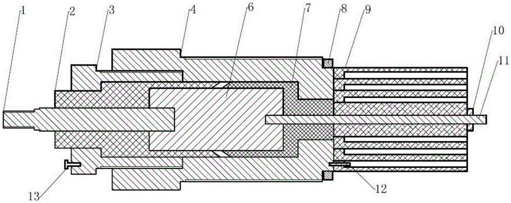
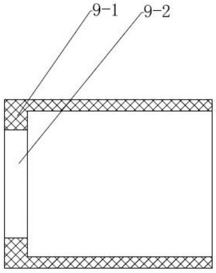
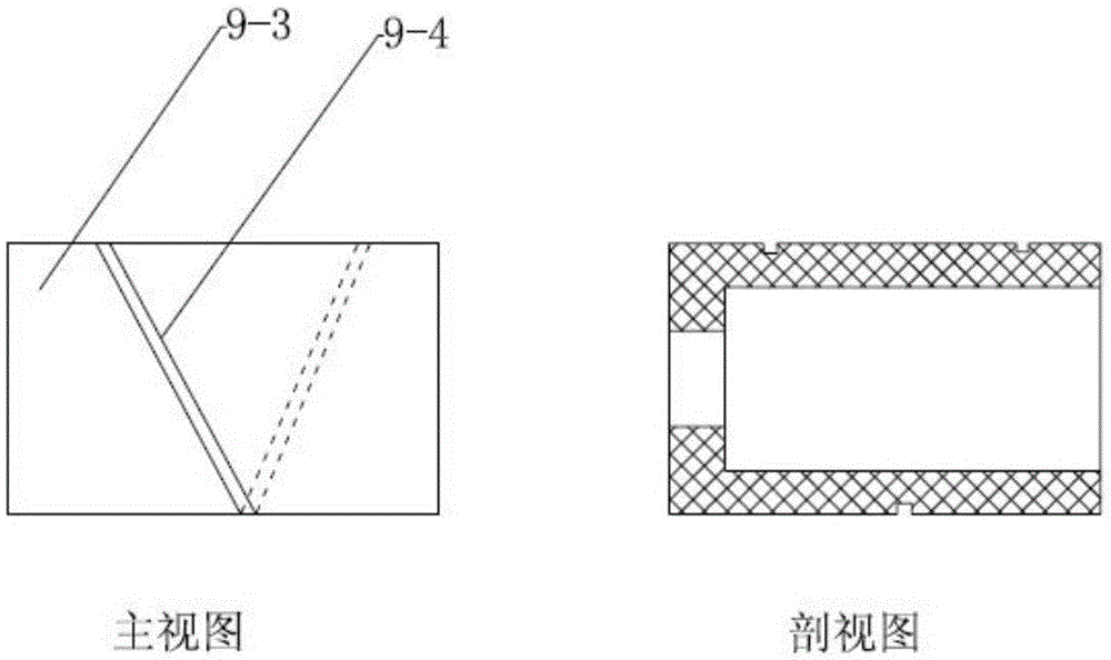
[0020] Such as figure 1 As shown, the preferred embodiment of the bottom multilayer plasma ignition device of the present invention includes an external ignition electrode rod 1, an outer end of an insulating sealing sleeve 2, an insulating sleeve compression screw plug 3, a screw plug body 4, an electrode compression block 6, The inner end of the insulating sealing sleeve 7, the sealing gasket 8, the cylindrical multi-layer plasma generator 9, the nut 10, the positive ignition needle 11, the negative ignition needle 12, and the negative terminal bolt 13. The ignition electrode rod 1 is a steel cylinder, one end of which is a necked external thread, which is connected to the ignition electrode by means of bolt fastening, and the external thread at the other end is connected to the electrode pressing block 6 . The sealed outer end 2 ...


PUM


Abstract

The invention discloses a plasma ignition device with a multilayer bottom and belongs to the field of explosive fire ignition. By the plasma ignition device, injection area of plasma jet can be effectively enlarged, injection pressure can be controlled, generation amount of plasmas can be increased, and ignition consistency in incipient combustion of propellant powders can be realized. A cylindrical generator module can be mounted at the bottom of ammunition, so that test efficiency can be improved, and engineering of plasma ignition can be realized.

Description

technical field [0001] The invention belongs to the field of propellant ignition, and mainly relates to a device for generating plasma under the action of a high-power pulse power supply, in particular to a bottom multilayer plasma ignition device for propellant ignition. Background technique [0002] Electrothermal chemical gun, as a new concept barrel weapon, has many advantages in improving the internal ballistic performance of propellant charges. Relevant research institutions at home and abroad have carried out related research work. The ignition method adopted by the electrothermal chemical gun is plasma ignition, and its main emission energy is still the conventional propellant, so how to make the propellant instantaneously and comprehensively ignite under the action of plasma is particularly important. The existing plasma ignition device is usually a central plasma generator. The plasma generator is composed of a positive pole and a negative pole. The positive pole i...

Claims


Application Information

Patent Timeline
Patent Type & Authority Patents(China)
IPC IPC(8): F42B3/10
Inventor 张江波严文荣闫光虎赵晓梅赵煜华梁磊刘毅李强
Owner XIAN MODERN CHEM RES INST
Learn More