
Automatic clamping device for fry for vaccine injection
A clamping device and a fry technology, applied in the field of automatic fry clamping devices, can solve the problems of time-consuming and laborious, low inoculation efficiency, etc., and achieve the effects of accurate operation, strong reliability and high degree of automation
- Summary
- Abstract
- Description
- Claims
- Application Information
AI Technical Summary
Problems solved by technology
Method used
Image

Examples
Embodiment Construction
[0017] The present invention will be further described below in conjunction with drawings and embodiments.
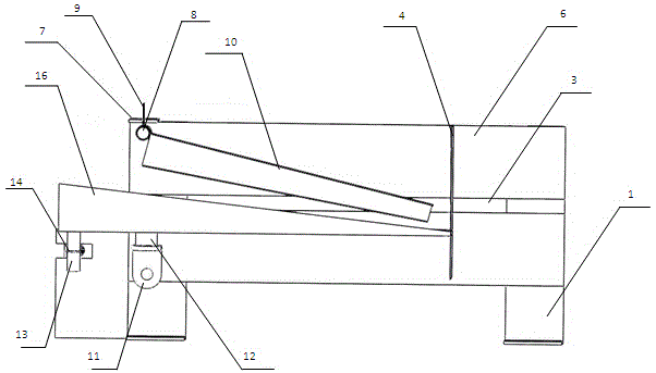
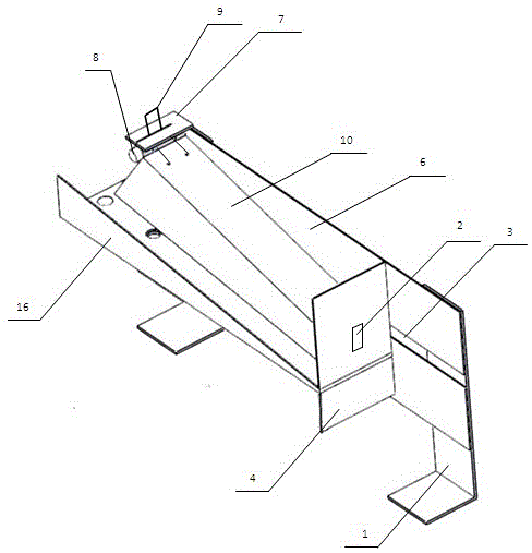
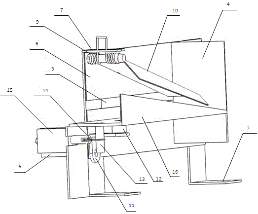
[0018] Such as figure 1 , figure 2 and image 3 As shown, the present invention includes two frames 1, an upper splint part and a lower splint part; wherein:
[0019] 1) Upper splint parts: including baffle plate 4, two side plates 6, torsion spring mounting plate 7, cylinder 8, torsion spring 9 and upper splint 10; two racks are equipped with upper and lower side plates 6, upper and lower There is a gap 3 between the two side plates 6, the upper edge of one end of the upper side plate is equipped with a torsion spring mounting plate 7, the cavity of the upper splint 10 with a trapezoidal cross-section faces downward, and the side of the upper splint 10 is evenly sleeved with the torsion spring 9 Rotation fit is formed on the cylinder 8, one end of the torsion spring 9 is inserted into the gap of the torsion spring mounting plate 7, the other end of the torsion spri...
PUM
 Abstract
Description
Claims
Application Information