
Touch screen and touch-control display device

A touch screen and touch position technology, which is applied in the directions of instruments, computing, and electrical digital data processing, can solve the problems of large frame width of touch display devices, poor touch effect, and large thickness of touch display devices. control effect, frame width reduction, and the effect of increasing the touch area

Active Publication Date: 2014-12-10
SHANGHAI TIANMA MICRO ELECTRONICS CO LTD +1
View PDF3 Cites 11 Cited by
  • Summary
  • Abstract
  • Description
  • Claims
  • Application Information

AI Technical Summary

Problems solved by technology

[0002] Nowadays, touch display devices such as mobile phones are becoming more and more popular. In actual use, it is found that there are problems such as poor touch effect, large frame width of touch display devices, and large thickness of touch display devices.

Method used


Image

  • Touch screen and touch-control display device
  • Touch screen and touch-control display device
  • Touch screen and touch-control display device

Examples


specific Embodiment approach

[0042] Method 1: If Figure 4a and Figure 4b As shown, a current scanning signal or a voltage scanning signal can be applied to pin 1 through one end of a signal unit 55, the other end of the signal unit is grounded, and pin 3 is also grounded at the same time. A switch SW (generally, the switch SW adopts a thin film transistor TFT) is arranged between the pin 6 and the pin 8, and the switch SW is in an off state when the coil does not need to be formed; the switch SW is in the conduction state when the coil needs to be formed, reaching Connect the pin 6 to the pin 8, so that the two first wires 221 respectively corresponding to the pin 6 and the pin 8 are connected, so that after the signal unit 55 applies a current to the pin 1 in one direction, the current flows to the first lead 221 connected to pin 8, and then through the turned-on switch SW, the current flows to the first lead 221 connected to pin 6, and then further flows to the first lead 222 connected to pin 3, thus...


PUM


Abstract

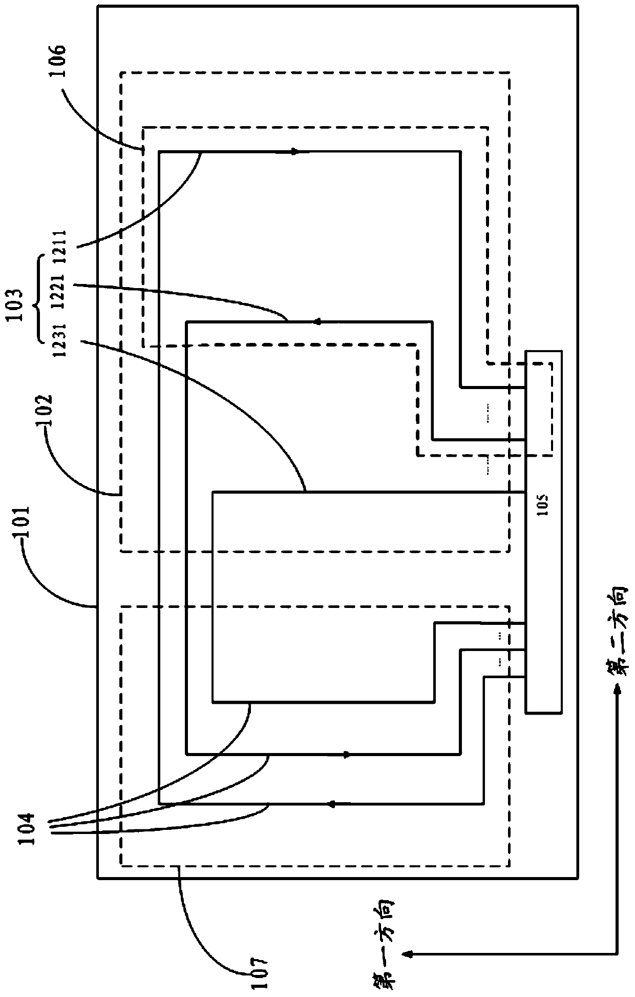
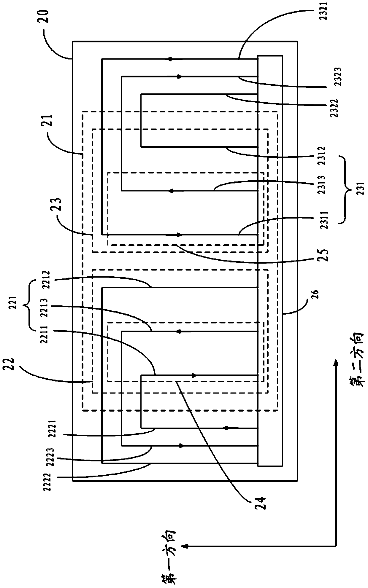
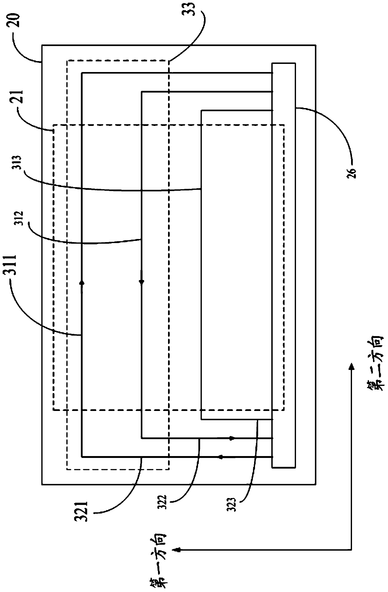
The invention discloses a touch screen and a touch-control display device. The touch screen and the touch-control display device comprises a plurality of first conducting wires and a plurality of second conducting wires, that are parallel to a first direction, and a plurality of third conducting wires parallel to a second direction, wherein each first conducting wire is correspondingly connected with a first leading wire; each second conducting wire is correspondingly connected with a second leading wire; each third conducting wire is correspondingly connected with a third leading wire; when electromagnetic touch happens, two optional first conducting wires are connected with each other; the current directions of two first leading wires that are correspondingly connected to the two optional first conducting wires are opposite to each other, so as to form a first coil; two optional second conducting wire are connected with each other; the current directions of two second leading wires that are correspondingly connected to the two optional second conducting wires are opposite, so as to form a second coil; two optional third conducting wires are connected with each other; the current directions of two third leading wires that are connected to the two optional third conducting wires are opposite, so as to form a third coil; the first coil and the second coil are used for detecting the coordinate of a touch position in the second direction; the third coil is used for detecting the coordinate of the touch position in the first direction.

Description

technical field [0001] The present invention relates to the technical fields of display and touch control, in particular to a touch screen and a touch display device. Background technique [0002] Nowadays, touch display devices such as mobile phones are becoming more and more popular. In actual use, it is found that there are problems such as poor touch effect, large frame width of the touch display device, and large thickness of the touch display device. Contents of the invention [0003] In view of this, the present invention provides a touch screen and a touch display device. [0004] A touch screen comprising: [0005] a substrate, including a display area; [0006] a first wire group, located on the substrate, the first wire group includes a plurality of first wires parallel to the first direction; [0007] a second wire group located on the substrate, the second wire group including a plurality of second wires parallel to the first direction; and [0008] a plur...

Claims


Application Information

Patent Timeline
Patent Type & Authority Applications(China)
IPC IPC(8): G06F3/046G06F3/044
Inventor 王敦博卢峰姚绮君金松林
Owner SHANGHAI TIANMA MICRO ELECTRONICS CO LTD
Learn More