Columnar body distinguishing method and columnar body distinguishing device

A columnar body and area technology, which is applied in the field of columnar body discrimination and columnar body discrimination device, can solve the problems of insufficient discrimination and difficulty in discrimination.

Active Publication Date: 2016-04-13
MITSUBISHI CHEM CORP
View PDF7 Cites 0 Cited by
  • Summary
  • Abstract
  • Description
  • Claims
  • Application Information

AI Technical Summary

Problems solved by technology

In such a case, it is difficult to distinguish the two types of columnar bodies from each other in the distinguishing device described in Patent Document 1.
In addition, even if the sieve described in Patent Document 2 is used to distinguish between two kinds of columnar bodies with little difference in length and thickness, the distinction cannot be sufficiently made.

Method used


Image

  • Columnar body distinguishing method and columnar body distinguishing device
  • Columnar body distinguishing method and columnar body distinguishing device
  • Columnar body distinguishing method and columnar body distinguishing device

Examples


Embodiment 1

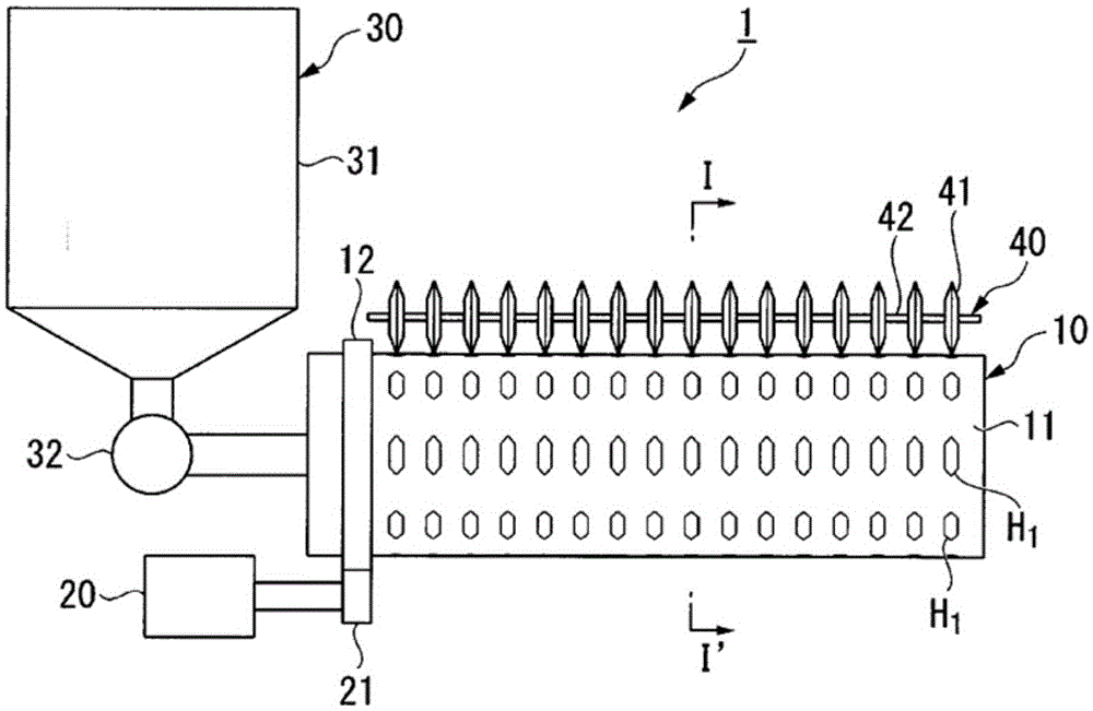
[0137] exist figure 1 and figure 2 In the columnar body distinguishing device 1 shown, use image 3 The opening hole H 1 The W is 5.5mm, L A 4.5mm, L B The 13.5 mm hexagonal cylindrical sieve 10 is divided into a catalyst cylinder (diameter 5 mm, length 5 mm) and a cylinder made of stainless steel spring (diameter (outer diameter) 6 mm, length 6 mm).

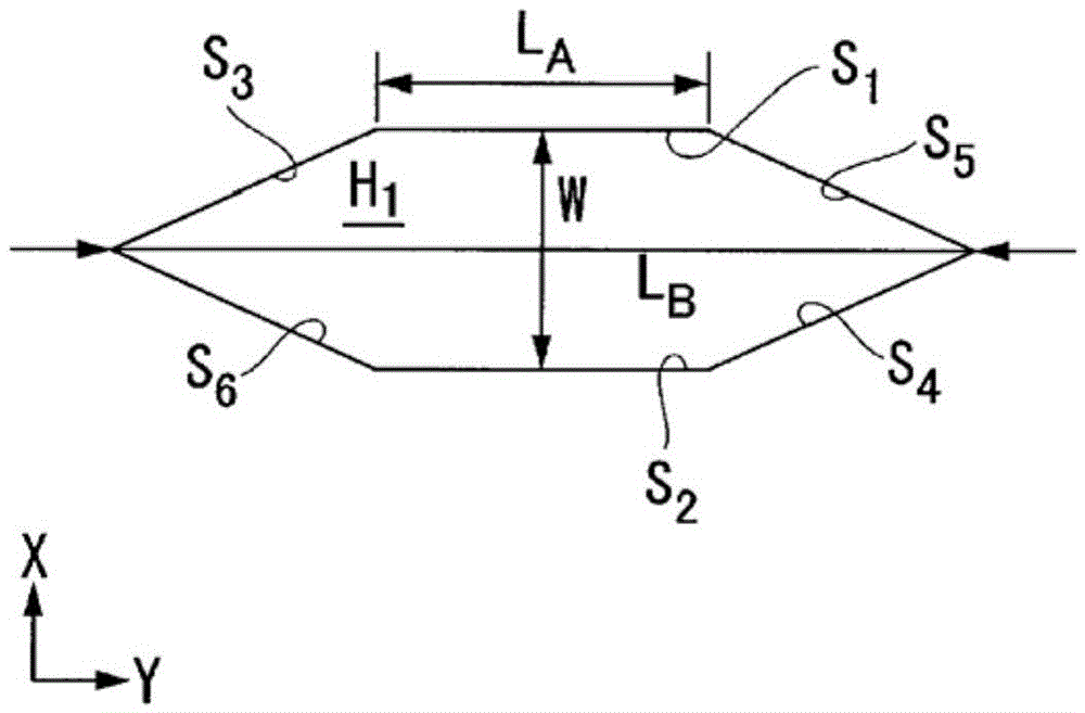
[0138] In addition, the opening hole H of the above-mentioned size of the cylindrical sieve 10 used 1 (a) to (d) are satisfied. which is:

[0139] (a) Open hole H 1 A pair of opposite sides (side S 1 with side S 2 , side S 3 with side S 4 , side S 5 with side S 6 ) are parallel and of the same length.

[0140] (b) Open hole H 1 edge S 1 with side S 2 The distance W is larger than the diameter and length of the catalyst cylinder and smaller than the diameter of the spring.

[0141] (c) side S 1 the length L A and the maximum length L of the hexagon in the Y direction B It is the following length, that is: wh...

Embodiment 2

[0155] A catalyst cylinder (diameter 5 mm, length 5 mm) and a stainless steel spring (diameter (outer diameter) 6 mm, length 6mm) were distinguished. During the differentiation process, a vibrator is used to vibrate the sieve section. In addition, similarly to Example 1, the discrimination was evaluated. The results are shown in Table 1.

[0156] In addition, since the flat sieve part was used in this example, the discrimination index E was calculated|required by substituting "remaining in the cylindrical sieve" with "remaining on the sieve part".

Embodiment 3

[0158] Align the opening holes of the cylinder sieve according to the Figure 17 The approximate slot shape shown is the opening hole H made into a slot 6 (L A : 5mm, L B : 28mm), such as Figure 19 As shown, except that the arrangement in the X direction is zigzag and the arrangement in the Y direction is in series, it is the same as in Example 1, and two types of cylinders are distinguished from each other. In addition, similarly to Example 1, the discrimination was evaluated. The results are shown in Table 1.


PUM


Abstract

The invention provides a columnar body distinguishing method and a columnar body distinguishing device, which can fully distinguish two types of cylinders with different lengths and thicknesses from each other, especially two types of cylinders with small differences in length and diameter. The columnar body distinguishing method and the columnar body distinguishing device (1) of the present invention utilize the sieve part (10) formed with the opening hole (H) of a specific shape, for the first columnar body, and the longer and thicker than the first columnar body The second column makes the distinction.

Description

technical field [0001] The present invention relates to a columnar body classification method and a columnar body classification device for classifying two types of columnar bodies different in length and thickness from each other. [0002] this application claims the priority of Japanese Patent Application No. 2012-062114 for which it applied in Japan on March 19, 2012, and uses the content here. Background technique [0003] In a reaction using a solid catalyst, the inside of the reactor is usually filled with a columnar body of the solid catalyst and a columnar body for dilution for adjusting the reaction. The solid catalyst whose reaction activity has decreased is taken out from the reactor in order to replace it, and in recent years, it is regenerated and reused without being disposed of. However, in order to reuse the used solid catalyst, it needs to be distinguished from the columnar body for dilution. [0004] As a device for distinguishing two kinds of columnar bo...

Claims


Application Information

Patent Timeline
Patent Type & Authority Patents(China)
IPC IPC(8): B07B1/46B07B1/22B07B1/52B07B1/54
CPCB07B1/22B07B1/46B07B1/4609B07B1/469B07B1/52B07B1/522B07B1/524B07B1/54B07B13/003
Inventor 田中伸吾田中茂穗福井友基
Owner MITSUBISHI CHEM CORP
Why Eureka
Try Eureka