Brake device

A brake device and electric brake technology, applied in the direction of brake transmission device, brake action start device, foot start device, etc., can solve problems such as power shortage

Inactive Publication Date: 2014-12-10
TOYOTA JIDOSHA KK +1
View PDF7 Cites 12 Cited by
  • Summary
  • Abstract
  • Description
  • Claims
  • Application Information

AI Technical Summary

Problems solved by technology

However, even electric braking mechanisms require countermeasures against problems such as disconnection, power shortage, etc.

Method used


Image

  • Brake device
  • Brake device
  • Brake device

Examples


Embodiment Construction

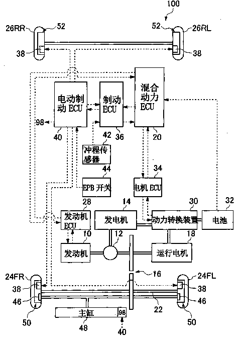
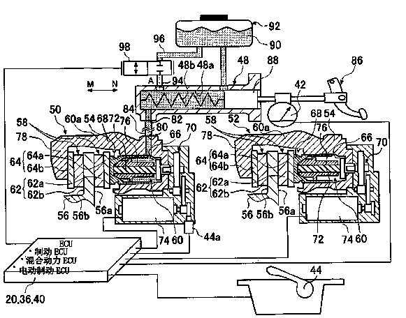
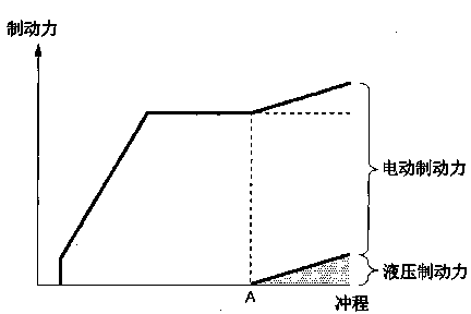
[0021] Exemplary embodiments of the present invention will be described in detail below with reference to the accompanying drawings. figure 1 is a structural illustration of a hybrid vehicle provided with a compound brake device according to an exemplary embodiment of the present invention. In the following specification, an example will be described in which electric braking force is mainly used as normal braking force, and regenerative braking force is used as appropriate. Also, in this specification, when sufficient electric braking force and regenerative braking force cannot be obtained, hydraulic braking force is used as backup braking force to ensure braking force. and, in figure 1 In the configuration example, the braking devices on the left and right front wheel sides with large braking force distribution are compound braking devices, which are equipped with electric braking mechanism and hydraulic braking mechanism, while the braking devices on the left and right rea...


PUM


Abstract

A brake device includes an electric brake mechanism that applies electric braking force, a hydraulic brake mechanism that applies hydraulic braking force, an electric brake ECU (40) that directs the electric brake mechanism to generate the electric braking force according to an operation amount of a brake pedal (86) operated by a driver, a master cylinder (48) in which a volume thereof changes according to the operation amount of the brake pedal (86), and that is able to deliver operating fluid (90) to the hydraulic brake mechanism (46) by a reduction in the volume, and a reservoir (92) that stores the operating fluid (90). The master cylinder (48) has a discharge port (94) that discharges the operating fluid (90) that is inside of the master cylinder (48) to the reservoir (92).

Description

technical field [0001] The present invention relates to a brake device, and more particularly, to a technique for controlling a brake device of a vehicle that mainly uses electric brakes. Background technique [0002] As a related brake device for a vehicle, it is known that a hydraulic brake device responds to the depression of the brake pedal by supplying the hydraulic pressure generated in the master cylinder to the wheel cylinder of the brake device of each wheel, thereby The friction members press against the brake disc to generate hydraulic braking force. Also, in recent years, with the practical use of electric vehicles and hybrid vehicles, the vehicle is decelerated or stopped using regenerative braking force generated when power is generated by regeneratively driving the motor to run (ie, running the motor), so The regenerative braking device has been put into practical application. In addition, an electric braking device that drives a gear train by a motor to mov...

Claims


Application Information

Patent Timeline
Patent Type & Authority Applications(China)
IPC IPC(8): B60T7/04B60T13/58B60T13/74
CPCB60T13/741B60T13/745B60T7/042B60T13/588
Inventor 山本真辅薮崎直树児玉博之
Owner TOYOTA JIDOSHA KK
Why Eureka
Try Eureka