
A pulse clock generation logic with built-in level shifter and programmable rising edge and pulse width

A technology of pulse clock and programming pulse, applied in the field of pulse clock and pulse clock generation

Inactive Publication Date: 2014-12-10
QUALCOMM INC
View PDF4 Cites 6 Cited by
  • Summary
  • Abstract
  • Description
  • Claims
  • Application Information

AI Technical Summary

Problems solved by technology

Conventional pulsed clock implementations are not well suited to meet these conflicting requirements for read and write operations on memory cells

Method used


Image

  • A pulse clock generation logic with built-in level shifter and programmable rising edge and pulse width
  • A pulse clock generation logic with built-in level shifter and programmable rising edge and pulse width
  • A pulse clock generation logic with built-in level shifter and programmable rising edge and pulse width

Examples


Embodiment Construction

[0019] Several aspects of the invention are disclosed in the following description and related drawings directed to specific embodiments of the invention. Alternative embodiments may be devised without departing from the scope of the present invention. Additionally, well-known elements of the invention will not be described in detail or will be omitted so as not to obscure the relevant details of the invention.

[0020] The word "exemplary" is used herein to mean "serving as an example, instance, or illustration." Any embodiment described herein as "exemplary" is not necessarily to be construed as preferred or advantageous over other embodiments. Likewise, the term "embodiments of the invention" does not require that all embodiments of the invention include the discussed feature, advantage or mode of operation.

[0021] The terminology used herein is for the purpose of describing particular embodiments only and is not intended to be limiting of embodiments of the invention. ...


PUM


Abstract

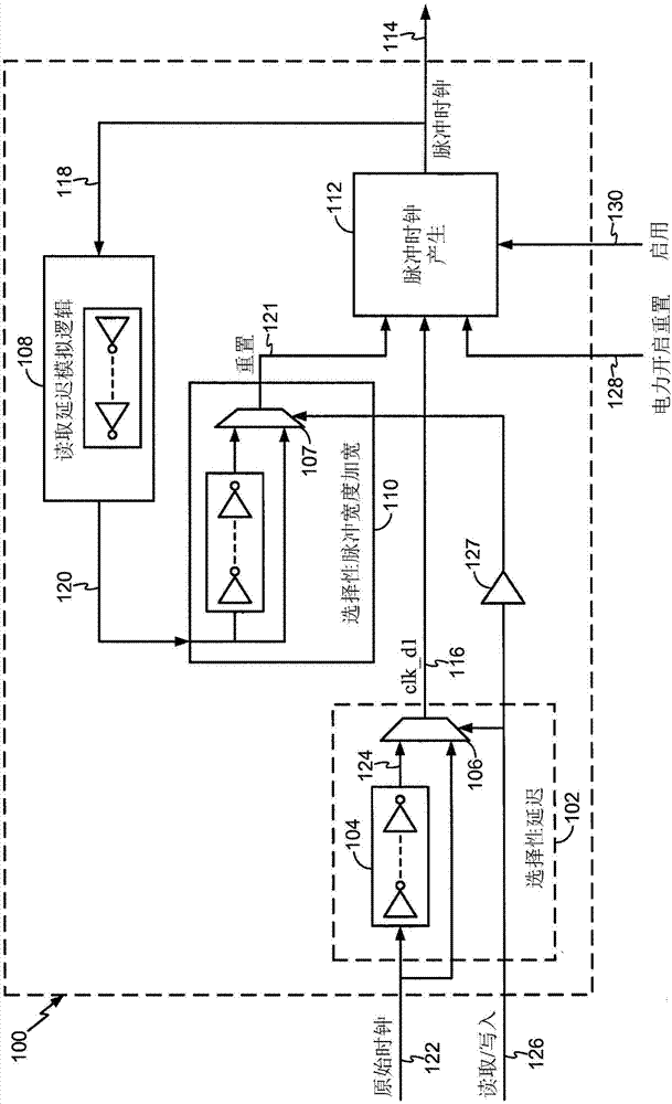
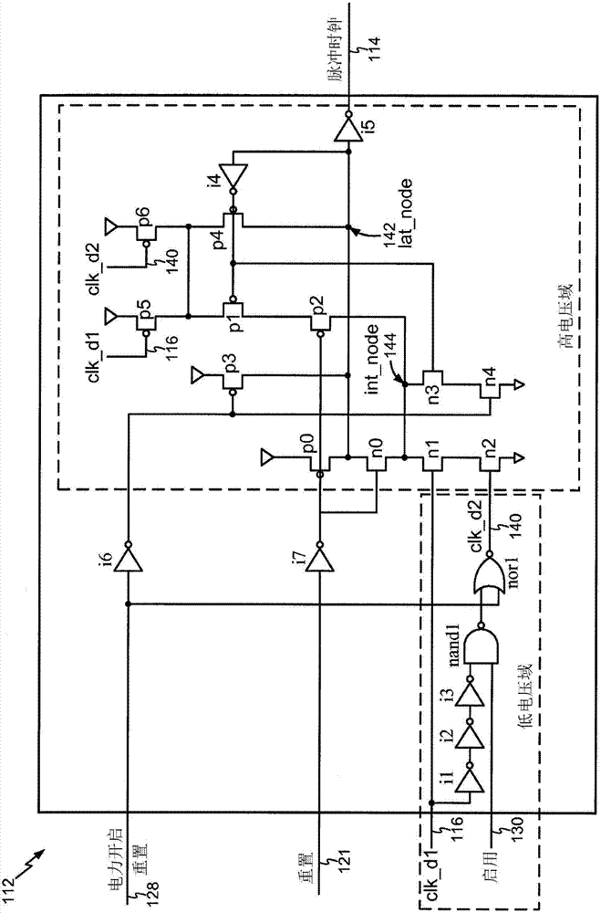
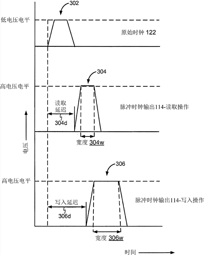
Systems and methods for generating pulse clocks with programmable edges and pulse widths configured for varying requirements of different memory access operations. A pulse clock generation circuit includes a selective delay logic to provide a programmable rising edge delay of the pulse clock, a selective pulse width widening logic to provide a programmable pulse width of the pulse clock, and a built-in level shifter for shifting a voltage level of the pulse clock. A rising edge delay for a read operation is programmed to correspond to an expected read array access delay, and the pulse width for a write operation is programmed to be wider than the pulse width for a read operation.

Description

technical field [0001] The disclosed embodiments generally relate to pulsed clock generation. More specifically, exemplary embodiments relate to generating pulse clocks with programmable edges and pulse widths configured for varying requirements of different memory access operations. Background technique [0002] The increasing demand for extended battery life and high processing speed in the handheld device and mobile phone industries has created a corresponding demand for low power and efficient memory systems. To save power, the on-chip memory is limited to low supply voltage levels. [0003] However, conventional memory cells, such as 6-transistor static random access memory (6T-SRAM), cannot operate at extremely low voltages. A common solution involves the use of multiple voltage domains so that memory cells can operate at relatively higher voltage levels while other on-chip logic can operate at lower voltages. To implement multiple voltage domains, level shifters ar...

Claims


Application Information

Patent Timeline
Patent Type & Authority Applications(China)
IPC IPC(8): G06F1/04G11C7/22G11C11/419
CPCG11C11/419G11C7/222G06F1/04G11C11/418G11C11/417
Inventor 葛绍平柴家明史蒂芬·艾德华·李莱斯拉姆·V·阮杰弗里·赫伯特·费希尔
Owner QUALCOMM INC
Learn More