Vertical type lathe and milling machine worktable with brake function

A technology of braking function and worktable, applied in manufacturing tools, metal processing equipment, metal processing machinery parts, etc., can solve the problems of inaccurate positioning and worktable deflection, and achieve the effect of good shock absorption capacity and large deformation capacity.

Inactive Publication Date: 2014-12-17
NANTONG JINGDING CNC EQUIP
View PDF0 Cites 2 Cited by
  • Summary
  • Abstract
  • Description
  • Claims
  • Application Information

AI Technical Summary

Problems solved by technology

At present, when vertical lathes and milling machines are working, it is necessary to stop the machine tool table by relying on the traditional motor self-locking, but this will face the problem of inaccurate positioning and the deviation of the table caused by the transmission hard brake. Therefore, there is a need for a technology on the market to make up for this deficiency

Method used


Image

  • Vertical type lathe and milling machine worktable with brake function
  • Vertical type lathe and milling machine worktable with brake function
  • Vertical type lathe and milling machine worktable with brake function

Examples


Embodiment 1

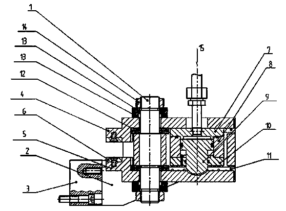
[0027] On the basis of the above structure, the present invention adds a limiting device 23 , a locking module 24 , a driving device 25 , and a fixed support 2 .

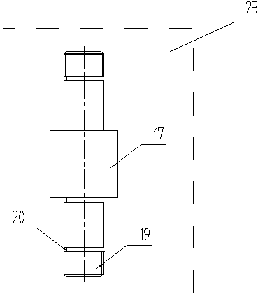
[0028] The concrete structure of limiter 23 is as figure 2 As shown: the limiting device 23 is a locking rod 1, the locking rod 1 is an optical axis, and the outer circular surface in the middle of the optical axis is provided with a flange 17 through integral molding, and the length of the flange 17 is the entire optical axis 1 / 3 of the length, the two ends of the optical axis 18 are respectively provided with threads 19, the length of the threads 19 is 1 / 6 of the length of the entire optical axis, and the rear ends of the two threads 19 are respectively provided with thread grooves 20, and the locking rod 1 of this device Both ends are provided with threads 19 to be connected with lock nuts 14, so that the degree of tightness of the device can be adjusted.

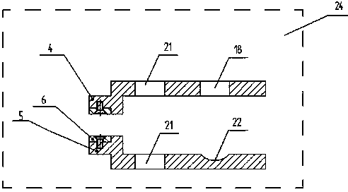
[0029] The concrete structure of locking module 24...

Embodiment 2

[0033] On the basis of Embodiment 1, the present invention also increases a heightening block 3 .

[0034] The concrete structure of heightening block 3 is as figure 1 Shown: heightening block 3 is a rectangular plate, and heightening block 3 is directly connected with workbench 16 by bolts, setting heightening block 3 can easily adjust the height that this device is installed on the workbench.

[0035] The specific connection relationship between the heightening block 3 and the device is as follows: the fixed support 2 and the heightening block 3 are integrally formed, and the braking device is connected with the fixed support 2 by a fixed manner.

[0036] The specific connection relationship between the brake device and the workbench is as follows: this device uses two brake devices to be installed on the radial flange of the workbench 16 in a diagonally symmetrical manner, specifically the upper locking block 4 and the lower locking block 5 left The notch space formed ...


PUM


Abstract

The invention discloses a vertical type lathe and milling machine worktable with a brake function. The worktable comprises a worktable body. The worktable is characterized by also comprising a brake device, wherein the brake device is arranged on the radial flange of the worktable body. The device has the advantages that the problem of inaccurate positioning caused by using the traditional motor self-locking to guarantee the locking of the worktable and the problem of deflection of the worktable caused by hard brake of transmission are solved; the two ends of a locking rod are provided with threads and are connected with locking nuts, so the elasticity of the device can be adjusted; a hydraulic system is used for driving, the sufficient pressure is guaranteed, and the stable running of equipment is guaranteed; a disc spring is arranged, and is used for bearing the axial load with larger change range, the deformation of unit size is larger, and the buffer and vibration-absorbing capabilities are realized; a heightening gasket is arranged, so the installation height of the device on the worktable can be conveniently adjusted.

Description

technical field [0001] The invention relates to numerical control equipment, in particular to a vertical turning and milling machine workbench with a braking function. Background technique [0002] CNC machine tool is the abbreviation of numerical control machine tool, which is an automatic machine tool equipped with a program control system. The control system can logically process programs with control codes or other symbolic instructions, decode them, express them in coded numbers, and input them into the numerical control device through the information carrier. After calculation and processing, various control signals are sent by the numerical control device to control the movement of the machine tool, and the parts are automatically processed according to the shape and size required by the drawing. CNC machine tools solve complex, precise, small-batch, and multi-variety parts processing problems. It is a flexible, high-efficiency automatic machine tool that represen...

Claims


Application Information

Patent Timeline
Patent Type & Authority Applications(China)
IPC IPC(8): B23Q1/28
CPCB23Q1/28
Inventor 孙美华刘永晨杨雷
Owner NANTONG JINGDING CNC EQUIP
Why Eureka
Try Eureka