
Drilling chuck correcting method

A correction method and drill chuck technology are applied in the field of drill chuck correction, which can solve problems such as hidden dangers in production, yaw, and excessive use of drill chucks, and achieve the effect of solving yaw

Inactive Publication Date: 2015-06-17
铜陵市永生机电制造有限责任公司
View PDF5 Cites 0 Cited by
  • Summary
  • Abstract
  • Description
  • Claims
  • Application Information

AI Technical Summary

Problems solved by technology

[0002] In industrial production, if the drill chuck is used for too long, it will cause deflection. If it is not repaired in time, it will bring hidden dangers to production.

Method used


Image

  • Drilling chuck correcting method

Examples


Embodiment Construction

[0012] The specific embodiments of the present invention will be described in detail below in conjunction with the accompanying drawings.

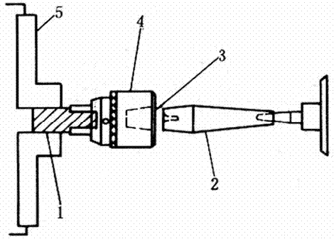
[0013] like figure 1 Shown, a drill chuck calibration method, the method steps are as follows:

[0014] a. Install the chuck taper shank 2 between the two centers on the lathe, place the small tool holder to the correct angle, and turn the taper shank to the correct angle;

[0015] b. Then install and clamp a bar 1 on the chuck 5, drive out the part that can be clamped by the drill chuck, and clamp the chuck 4 to the rod 1;

[0016] c. The small tool holder is still renovating the taper hole 3 of the chuck 4 at the angle of turning the taper handle 2, and the chuck has been corrected at this time;

[0017] d. Insert the taper shank into the taper hole of the chuck, and the other end is positioned by the top of the tailstock. There is no swing phenomenon during the turning of the car, which shows that the calibration of the chuck is corre...


PUM


Abstract

The invention discloses a drilling chuck correcting method. A chuck taper handle 2 is clamped between two tips on a lathe, and a small tool post is placed in a correct angle for turning the taper handle to a correct angle; then, a bar 1 is clamped on a clamping disc 5, a part capable of being clamped by a drilling chuck is screwed out, and the bar 1 is clamped by a chuck 4; the small tool post still finishes a taper hole 3 of the chuck 4 by the angle of turning the taper handle 2, and the correction of the chuck is finished; and the taper handle is inserted into the taper hole of the chuck, and the other end is positioned by a tail base tip, so that no swinging phenomenon is generated in the turning rotation to express the chuck correcting accuracy. The method is simple and practical, and can effectively solve the deflection problem of the drilling chuck.

Description

technical field [0001] The invention relates to a drill chuck correction method. Background technique [0002] In industrial production, if the drill chuck is used for too long, it will cause deflection. If it is not repaired in time, it will bring hidden dangers to production. Contents of the invention [0003] The object of the present invention is to provide a drill chuck calibration method. [0004] The technical scheme adopted in the present invention is: a drill chuck correction method, the method steps are as follows: [0005] a. Install the chuck taper shank 2 between the two centers on the lathe, place the small tool holder to the correct angle, and turn the taper shank to the correct angle; [0006] b. Then install and clamp a bar 1 on the chuck 5, drive out the part that can be clamped by the drill chuck, and clamp the chuck 4 to the rod 1; [0007] c. The small tool holder is still renovating the taper hole 3 of the chuck 4 at the angle of turning the taper ...

Claims


Application Information

Patent Timeline
IPC IPC(8): B23P6/00
CPCB23P6/00
Inventor 朱俊生
Owner 铜陵市永生机电制造有限责任公司
Learn More