Integrated design method for hypersonic-velocity wave rider fuselage and air inlet channel

A hypersonic, air inlet technology, which is used in the combustion of the air inlet of the power plant, the air inlet of the turbine/propulsion device, and aircraft parts, etc., can solve the problem that the high lift-to-drag ratio characteristics of the waverider cannot be fully utilized.

Active Publication Date: 2014-12-17
NAT UNIV OF DEFENSE TECH
View PDF4 Cites 39 Cited by
  • Summary
  • Abstract
  • Description
  • Claims
  • Application Information

AI Technical Summary

Problems solved by technology

In this conventional waverider-inlet integrated design method, only the waverider is used as the precursor of the hypersonic vehicle, and the high lift-to-drag ratio characteristics of the waverider cannot be fully utilized.

Method used


Image

  • Integrated design method for hypersonic-velocity wave rider fuselage and air inlet channel
  • Integrated design method for hypersonic-velocity wave rider fuselage and air inlet channel
  • Integrated design method for hypersonic-velocity wave rider fuselage and air inlet channel

Examples


Embodiment Construction

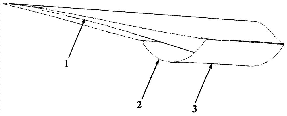
[0031] The present invention provides a method for the integrated design of a hypersonic waverider fuselage and an air inlet. The waverider is used as the entire hypersonic aircraft fuselage, which is referred to as the waverider fuselage. At the same time, it is tracked with the streamline and turned outward to the air inlet. Integration, including the following steps:

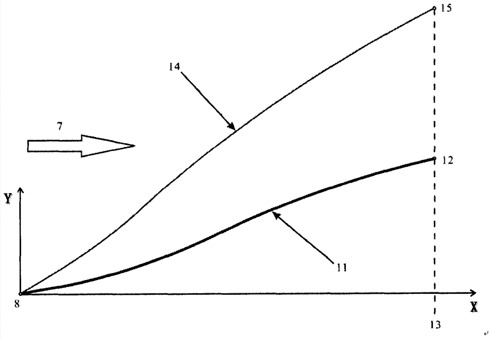
[0032] Step S1, designing the pointed rotor, and solving the supersonic axisymmetric flow field around the zero angle of attack pointed rotor.

[0033] Such as image 3 As shown, let the curve 11 be the generatrix of the pointed rotor, the starting point of the bus is point 8, and the end point of the bus is point 12. Under the action of zero angle of attack and supersonic incoming flow 7, the pointed rotor can produce forward Edge shock wave 14, the end point of leading edge shock wave 14 on the bottom cross-section 13 of the pointed rotor is point 15.

[0034] The condition of the supersonic incoming flow...


PUM


Abstract

The invention discloses an integrated design method for a hypersonic-velocity wave rider fuselage and an air inlet channel. A wave rider is used as a whole hypersonic-velocity aircraft fuselage and is integrated with the flow line tracking outer steering air inlet channel. The integrated design method comprises the following steps: designing a pointed-end rotary body and solving a supersonic-velocity axially symmetric flow field around the zero-incidence pointed-end rotary body; designing an inner flow and outer flow integrated axially symmetric standard flow field in the supersonic-velocity axially symmetric flow field around the zero-incidence pointed-end rotary body; carrying out flow line tracking in the inner flow and outer flow integrated axially symmetric standard flow field from a front leading edge of the wave rider fuselage and an inlet molded line of the air inlet channel to generate an integrated shape. With the adoption of the technical scheme, the lift-drag ratio property of the wave rider can be sufficiently expressed.

Description

technical field [0001] The invention relates to the technical field of aerodynamic shape design of a hypersonic aircraft, in particular to an integrated design method of a hypersonic waverider fuselage and an air inlet. Background technique [0002] An air-breathing hypersonic vehicle refers to an aircraft with a flight Mach number greater than 5, powered by an air-breathing engine or a combined engine, and capable of long-distance flight in the atmosphere and across the atmosphere. Its application forms include hypersonic cruise missiles, hypersonic Manned / unmanned aircraft and aerospace aircraft and other aircraft. [0003] A large number of studies since the 1960s have fully demonstrated that the integrated design of the propulsion system and the airframe is the key to the realization of hypersonic flight, and it is one of the key technologies to be solved urgently in hypersonic vehicle technology, and the core of airframe / propulsion system integration It is the integrat...

Claims


Application Information

Patent Timeline
Patent Type & Authority Applications(China)
IPC IPC(8): B64F5/00B64D33/02F02C7/04
Inventor 丁峰柳军沈赤兵黄伟李开刘珍
Owner NAT UNIV OF DEFENSE TECH
Why Eureka
Try Eureka