
Machine tool having extendable cover

A technology of telescopic cover and machine tool, which is applied in the direction of manufacturing tools, mechanical equipment, metal processing machinery parts, etc., and can solve the problems of unexplained telescopic cover assembly, etc.

Inactive Publication Date: 2014-12-24
FANUC LTD
View PDF2 Cites 2 Cited by
  • Summary
  • Abstract
  • Description
  • Claims
  • Application Information

AI Technical Summary

Problems solved by technology

However, in the method of directly fixing the both ends of the telescoping cover to the table, saddle, pillar or bed, it is impossible to secure a sufficient amount of adjustment in the front, rear, left, right, up, and down directions.
The structure of the telescopic cover is disclosed in Japanese Patent Laid-Open No. 7-60593 or Japanese Patent Laid-Open No. 2003-236731, but in these prior art, the assembly of the telescopic cover is not described.

Method used


Image

  • Machine tool having extendable cover
  • Machine tool having extendable cover
  • Machine tool having extendable cover

Examples


Embodiment Construction

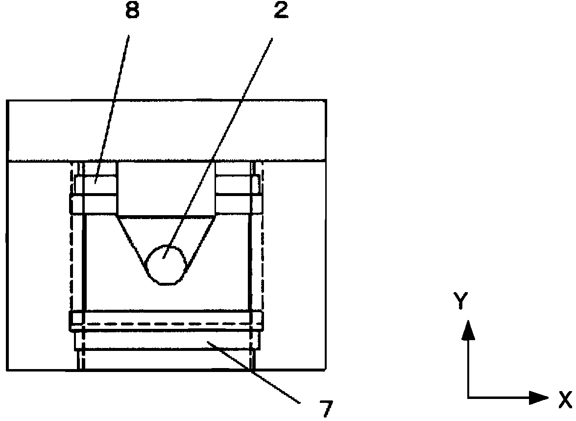
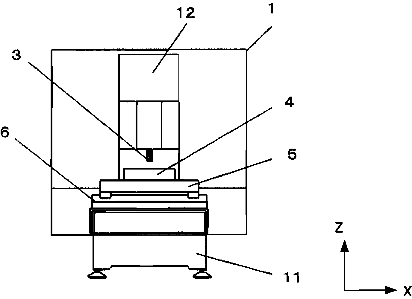
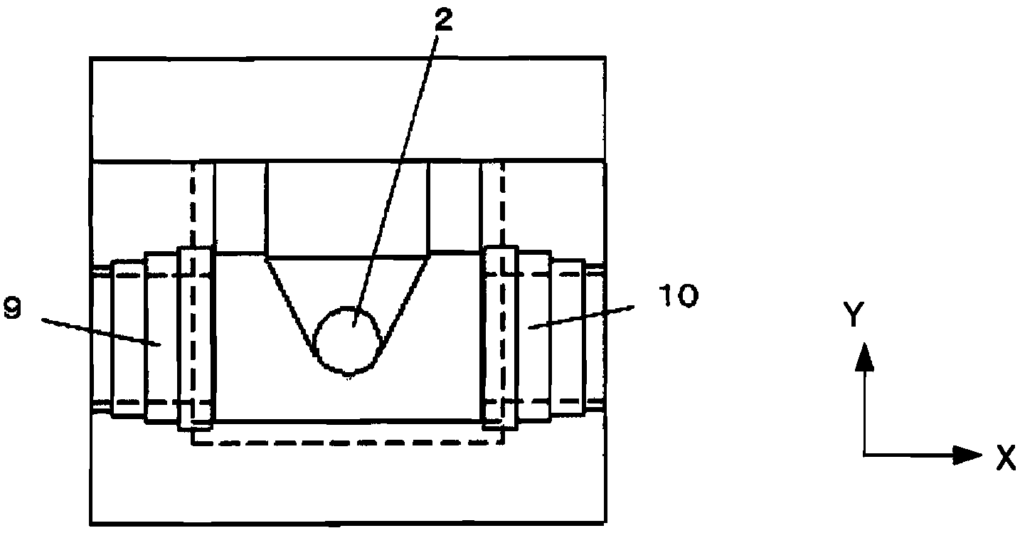
[0030] use Figure 1A and Figure 1B A first example of a machine tool having a telescopic cover (telescopic cover) will be described.

[0031] The processing area formed on the upper part of the bed 11 is covered by the guard plate 1 . A column 12 on which the main shaft 2 is mounted is erected on the bed 11 . A tool 3 is mounted on the spindle 2 . The spindle 2 is controlled so as to be able to move up and down relative to the table 5 (that is, to be able to move in the Z-axis direction). A saddle 6 is supported on the bed 11 , and a workbench 5 is supported on the saddle 6 . The workpiece 4 is placed on the table 5 . The saddle 6 moves in the Y-axis direction on the bed 11 , and the table 5 moves in the X-axis direction perpendicular to the Y-axis on the saddle 6 .

[0032] Symbols 7 and 8 are telescopic covers, which prevent the chips and cutting fluid generated during the processing of the workpiece 4 from scattering in a wide range. The movable end) is attached to...


PUM


Abstract

The invention provides a machine tool having an extendable cover. The machine tool has a telescopic cover. One end of the telescopic cover is fixed to the machine tool via a cover supporting member. In the cover supporting member, through holes through which fixing bolts pass are formed on a surface to be fixed to the telescopic cover and a surface to be attached to the machine tool. Gaps between the through holes and fixing bolts are used to adjust the attachment position of the cover supporting member with respect to the machine tool and the position of the telescopic cover with respect to the cover supporting member.

Description

technical field [0001] The invention relates to machine tools with bellows. Background technique [0002] In machine tools, Japanese Patent Laid-Open No. 7-60593 or Japanese Patent Laid-Open No. 2003-236731 is known in order to prevent chips generated during processing from accumulating on workbenches, saddles, or ball screws for driving pillars. , A telescopic cover (telescopic cover) covering these components is provided. [0003] When the telescoping cover is arranged on the machine tool, it is generally adopted to install one end (fixed end) on the workbench, saddle or pillar, and install the other end (movable end) on the saddle or bed. [0004] In order to make the machine tool work efficiently, each part of the machine is moved at high speed. When installing the telescoping cover on the machine tool, when the telescopic cover is fixed on the machine tool in a state where the position is poorly adjusted and twisted between one end (moving end) and the other end (fixe...

Claims


Application Information

Patent Timeline
Patent Type & Authority Applications(China)
IPC IPC(8): B23Q11/08
CPCB23Q11/0825Y10T74/219
Inventor 长尾明彦
Owner FANUC LTD
Learn More