Cutting blade position adjustment mechanism and cutting edge-replaceable cutting tool

A technology for adjusting mechanisms and cutting tools, which is applied in the manufacture of tools, milling cutters, metal processing, etc., can solve the problems of reducing the number of regrinding, difficult to ensure processing accuracy, and difficult fine-tuning of cutting edges, so as to improve processing accuracy and prolong Tool life and the effect of adjustment work

Active Publication Date: 2015-12-02
MITSUBISHI MATERIALS CORP
View PDF8 Cites 3 Cited by
  • Summary
  • Abstract
  • Description
  • Claims
  • Application Information

AI Technical Summary

Problems solved by technology

[0007] That is, in the above-mentioned cutting edge position adjustment mechanism, the fine adjustment of the cutting edge position can be realized by narrowing the thread pitch of the adjustment screw, and the processing accuracy can be improved. The adjustment work becomes troublesome, and the adjustment amount of the cutting edge position cannot be ensured to a large extent
More specifically, it is difficult to ensure the protrusion amount of the cutting edge when regrinding the cut

Method used


Image

  • Cutting blade position adjustment mechanism and cutting edge-replaceable cutting tool
  • Cutting blade position adjustment mechanism and cutting edge-replaceable cutting tool
  • Cutting blade position adjustment mechanism and cutting edge-replaceable cutting tool

Examples


Embodiment Construction

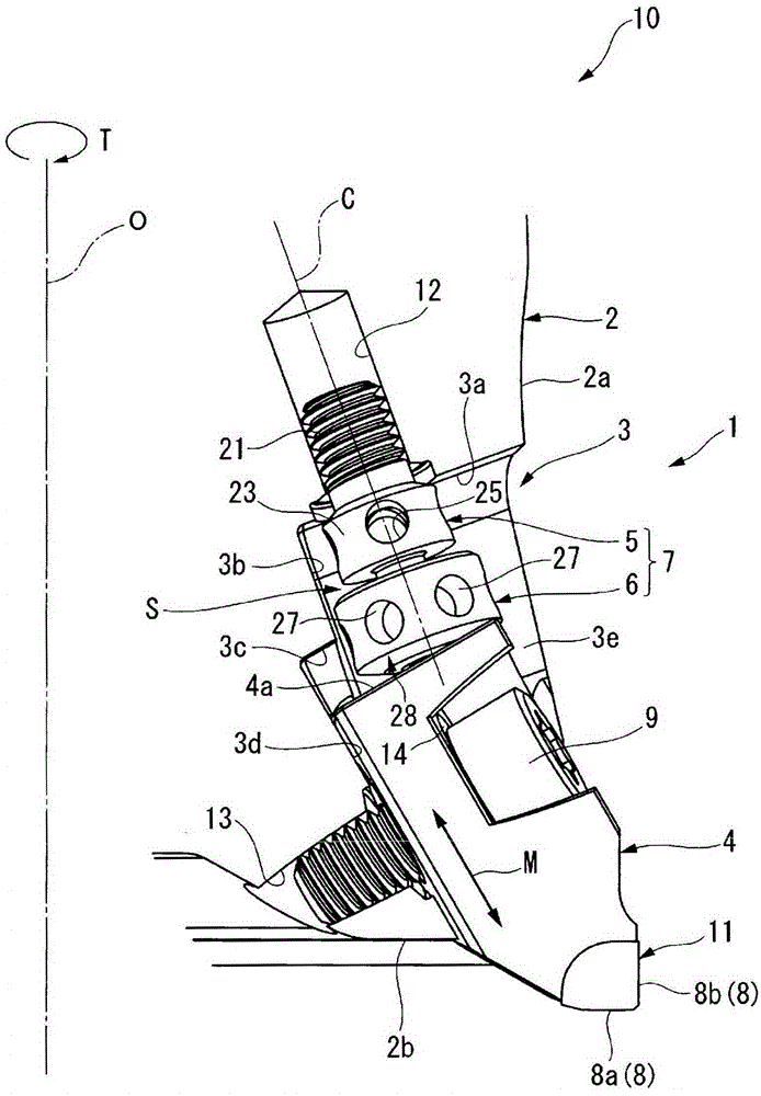
[0032] Hereinafter, a cutting edge position adjustment mechanism 1 according to an embodiment of the present invention and an indexable insert type cutting tool 10 using the same will be described with reference to the drawings.

[0033] The indexable insert type cutting tool 10 of the present embodiment is, for example, an indexable insert type face mill (indexable insert type milling tool) for finishing.

[0034] Such as figure 1 As shown, the indexable insert type cutting tool 10 has: a tool body 2, which is cylindrical or cylindrical (disc-shaped) and rotates around the tool axis O; a cutting edge member 4 is detachably installed on the The outer peripheral portion of the front end of the tool body 2, and the cutting edge 8 protrudes toward at least one of the tool front end side and the radially outer side of the tool; and the cutting edge position adjustment mechanism 1 moves the cutting edge member 4 relative to the tool body 2 to adjust the position of the cutting edg...


PUM


Abstract

The purpose of the present invention is to ensure that there is a large margin for positional adjustment of a cutting blade so as to increase the frequency of resharpening and prolong the life of the tool, and to simplify work for adjusting the cutting blade position and enable fine adjustment of the position of the cutting blade to improve machining precision. Provided is a cutting blade position adjustment mechanism (1) for moving a cutting blade member (4) mounted on a tool body (2) relative to the tool body (2) to adjust the position of a cutting blade (8) of the cutting blade member (4), characterized in that: the cutting blade position adjustment mechanism (1) is equipped with a shaft member (5) that extends between the tool body (2) and the cutting blade member (4) and threadably engages with the tool body (2) and a nut member (6) that threadably engages with the shaft member (5) and abuts the cutting blade member (4); a first screw section (21) that threadably engages with the tool body (2) and a second screw section that threadably engages with the nut member (6) are provided coaxially on the shaft member (5) at different positions along the direction of the axis line (C) of the shaft member (5); and the thread pitch of the first screw section (21) and the thread pitch of the second screw section are different from each other.

Description

technical field [0001] The invention relates to a cutting edge position adjustment mechanism and an indexable blade type cutting tool using the adjustment mechanism. Background technique [0002] In the past, for example, as shown in the following patent documents 1 and 2, it is known to have a tool body that rotates around the tool axis and a tool body that is detachably mounted on the front end outer peripheral portion of the tool body and that has a cutting edge toward the front end side of the tool and the tool body. Indexable insert type cutting tools such as face milling cutters with cutting edge parts projecting radially outward. [0003] The indexable insert type cutting tools in the following patent documents 1 and 2 are equipped with a cutting edge position adjustment mechanism that adjusts the position of the cutting edge by moving the cutting edge member relative to the tool body. Specifically, as the cutting edge position adjustment The mechanism has an adjustm...

Claims


Application Information

Patent Timeline
IPC IPC(8): B23C5/24B23B29/034
CPCB23B29/03407B23B2260/056B23C5/2472B23C2260/28
Inventor 作山徹齐藤贵宣
Owner MITSUBISHI MATERIALS CORP
Why Eureka
Try Eureka