elevator

A technology for elevators and elevator cars, applied in the field of elevators, can solve problems such as damage to threaded parts, and achieve the effect of stabilizing and maintaining the service life

Inactive Publication Date: 2016-08-24
HITACHI LTD
View PDF7 Cites 0 Cited by
  • Summary
  • Abstract
  • Description
  • Claims
  • Application Information

AI Technical Summary

Problems solved by technology

In addition, in the structure shown in Patent Document 2, in the state where the force generated by the moment of the adjacent wire rope acts on the threaded part of the rod, relative movement occurs between the threaded part and the bracket, which may cause the thread partially damaged

Method used


Image

  • elevator
  • elevator
  • elevator

Examples


no. 1 example

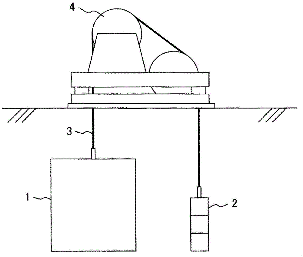
[0050] exist figure 1 In the elevator shown, the wire rope is wound in a 1:1 winding method, and the elevator car 1 and the counterweight 2 are connected by a wire rope 3 . The wire rope 3 is wound around a hoist 4 , and the hoist 4 drives the wire rope 3 to raise and lower the elevator car 1 and the counterweight 2 .

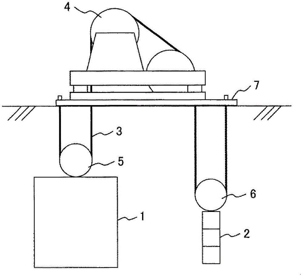
[0051] exist figure 2 In the elevator shown, the steel wire rope is wound with a 2:1 winding method, and the steel wire rope 3 is suspended via a movable pulley, namely pulley 5, installed on the elevator car 1, and a movable pulley, namely, pulley 6, installed on the counterweight 2. The elevator car 1 and the counterweight 2, the ends of the wire ropes 3 are installed on the top base 7 as a support member. The ends of the wire ropes 3 can also be installed directly on beam members as supporting members of the building.

[0052] exist figure 1 with figure 2 In the elevator structure shown, the installation parts of the wire rope 3 are different, some ...

no. 2 example

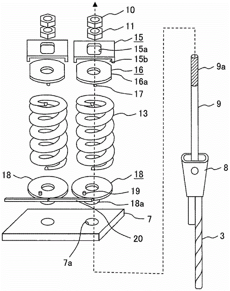
[0061] Figure 4 Shows the second embodiment of the present invention. A convex portion 22a and two screw holes 22b are provided on the lower portion of the upper washer 22, and the screws 23 are fixed after tightening the nut 11 and applying a predetermined tension to the rod 9. The relative rotation of the nut 11 and the washer 22 can be prevented by making the end surface of the nut 11 which is the nut for setting the tension among the double nuts contact the side surface of the screw 23 .

[0062] The protrusion 22 a of the washer 22 engages with the end of the spring 13 , thereby preventing the washer 22 and the spring 13 from rotating relative to each other. In addition, by engaging the convex portion 19 of the washer 18 with the end of the spring 13 , it is possible to prevent the relative rotation of the spring 13 and the washer 18 .

[0063] The torque transmitting member 20 is welded on the washer 18 . The torque generated by the wire rope 3 is transmitted to the ...

no. 3 example

[0065] Figure 5 A third embodiment of the present invention is shown. The nuts used for fastening in the double nuts, that is, the nut 11 and the washer 24 are fixed together by welding in advance, and there is no relative rotation between the two. Six holes 24a for inserting pins 25 are opened in the washer 24, and after tightening the nut 11 and applying a predetermined tension to the rod 9, the pins 25 are inserted into the holes 24a closest to the end of the spring 13. By engaging the spring 13 with the pin 25 , the relative rotation of the spring 13 and the washer 24 can be prevented. Other structures are the same as those of the second embodiment.


PUM


Abstract

An anti-revolving structure which is novel and prevents a rod piece at the end part of a steel wire rope of an elevator from revolving is provided. The adjustment amount of a threaded part for adjusting the length of a steel wire rope on the rod piece is formed necessarily. The invention provides an elevator comprising a plurality of steel wire ropes for connecting an elevator car and a counterweight and a winch for driving the steel wire ropes. The elevator also comprises a rod piece, a double nut structure, a first gasket, an elastic piece and a second gasket, wherein the rod piece is connected with the end parts of the plurality of steel wire ropes and passes through a hole in a support component for supporting the elevator car and the counterweight, and the double nut structure is formed of a first nut and a second nut and is in screw joint with a threaded part in a projection part of the rod piece. In addition, the elevator also has a snap-fit part for preventing counter rotation between the second nut and the first gasket, a snap-fit part for preventing counter rotation between the first gasket and the elastic piece, a snap-fit part for preventing counter rotation between the elastic piece and the second gasket, and a snap-fit part for preventing counter rotation between the second gasket and the support piece.

Description

technical field [0001] The present invention relates to an elevator that uses a plurality of wire ropes to raise and lower the elevator car and counterweight. Background technique [0002] The steel wire rope used in the elevator adopts a structure formed by twisting multiple steel wires. In the elevator, one end of the wire rope is connected to the elevator car, and the other end is connected to the counterweight, and the wire rope is driven by the hoist to lift the elevator car, or the two ends of the wire rope are fixed to the structure of the building. At the top, pulleys are respectively arranged on the elevator car and the counterweight, so that the steel wire rope passes through the pulleys to form a movable pulley, thereby making the elevator car and the counterweight go up and down. No matter which structure is adopted, when the elevator car is raised and lowered, the steel wire rope is repeatedly bent under tension. Therefore, during use, as the fatigue of the st...

Claims


Application Information

Patent Timeline
Patent Type & Authority Patents(China)
IPC IPC(8): B66B7/10
Inventor 浅井大辅
Owner HITACHI LTD
Why Eureka
Try Eureka