Coil frame and transformer using the coil frame

A coil bobbin and bobbin technology, applied in the field of transformers, can solve problems such as inability to perform height and adjustment, and achieve the effects of simplifying component management, ensuring the adjustment amount, and improving the bonding state

Active Publication Date: 2013-01-16
SUMIDA CORP
View PDF1 Cites 0 Cited by
  • Summary
  • Abstract
  • Description
  • Claims
  • Application Information

AI Technical Summary

Problems solved by technology

Therefore, the above structures all have the problem that fine height adjustment cannot be performed

Method used


Image

  • Coil frame and transformer using the coil frame
  • Coil frame and transformer using the coil frame
  • Coil frame and transformer using the coil frame

Examples


Embodiment Construction

[0032] Hereinafter, modes for implementing the present invention (hereinafter referred to as "embodiments") will be described in detail with reference to the drawings.

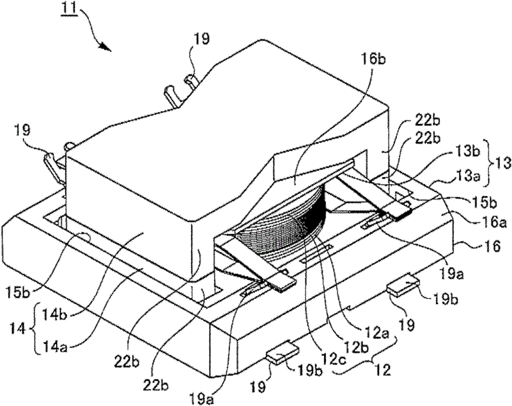
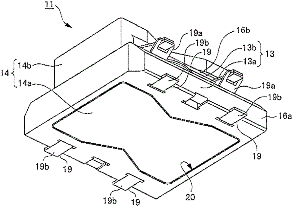
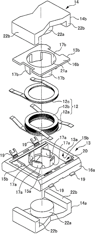
[0033] Figure 1 to Figure 6 shows a transformer as an embodiment of the present invention, figure 1 is a perspective view of the above-mentioned transformer viewed from the upper side, figure 2 is a perspective view of the above-mentioned transformer viewed from the lower side, image 3 is an exploded perspective view of the main parts of the above transformer, Figure 4 is a perspective view showing the coil bobbin of the above-mentioned transformer, Figure 5 Represents the bobbin of the above transformer, where Figure 5 (a) is a side view in the state where the coil is not assembled, Figure 5 (b) is a side view of the state where the coil is assembled, Figure 6 is along Figure 5 A cross-sectional view of line A-A in. In addition, in all descriptions of embodiment, the same code|symbol is attac...


PUM


Abstract

The invention provides a coil frame and a transformer using the coil frame. The coil frame can be used for reasonably dealing with multiple coiling parts with different winding turns or creepage distances. The coil frame has a roll core part (17) the periphery of which is provided with coils (12). The coil frame comprises a first half frame body (13a) and a second half frame body (13b). Each halfframe body (13a,13b) integrally comprises a flange part (terminal seat part 16a), an upper side flange part (16b) and at least two roll core members (17a, 17b) projecting at a right angle from the flange part. Furthermore, each half frame body (13a,13b) is assembled in a way that the roll core members (17a,17b) intersect between the two half frame bodies (13a,13b) and the flange parts slide alongthe direction where the flange parts are close to each other. Thus a cylindrical roll core part (17) is formed.

Description

technical field [0001] The present invention relates to a bobbin and a transformer using the bobbin, in particular to a bobbin capable of dealing with winding components such as various transformers or inductors with different numbers of winding turns or creepage distances, and a bobbin using the bobbin the transformer. Background technique [0002] Conventionally, there is known a transformer that can use a bobbin whose height can be adjusted (same as in the longitudinal direction, hereinafter the same), and one type of bobbin can be used for a variety of transformers (for example, refer to Patent Document 1). [0003] With regard to the transformer known in Patent Document 1, the skeleton main body and the base part forming the skeleton are separated from each other, and a plurality of annular recesses or external threads are formed on the outer periphery of the lower end part of the cylindrical part of the skeleton main body. In the support hole of the base portion throu...

Claims


Application Information

Patent Timeline
Patent Type & Authority Patents(China)
IPC IPC(8): H01F27/30H01F27/00
Inventor 佐佐木尚树
Owner SUMIDA CORP
Why Eureka
Try Eureka