Device for comprehensively preventing guide line from oscillating

An all-round, conductive technology, applied in the direction of mechanical vibration attenuation devices, etc., can solve the problems of shortened service life of the anti-vibration hammer, increased external force of the anti-vibration hammer, and reduced service life of the wire, so as to prevent vibration and galloping, enhance the anti-vibration effect, Effect of preventing conductor vibration

Active Publication Date: 2014-12-24
FUXIN POWER SUPPLY COMPANY STATE GRID LIAONING ELECTRIC POWER +1
View PDF7 Cites 4 Cited by
  • Summary
  • Abstract
  • Description
  • Claims
  • Application Information

AI Technical Summary

Problems solved by technology

[0003] There are many kinds of anti-vibration hammers at present, but most of them are composed of clamp splints, steel strands and cast iron hammer heads. In severe weather, the external force on the hammer head of the anti-vibration hammer is increased, and there is often a separation between the hammer head and the steel strand, which shortens the service life of the anti-vibration hammer and increases maintenance and replacement operations
[0004] At the same time, because the hammer head of the anti-vibration hammer is affected by external force, the influence of its own additional vibration and bending stress will cause the wire to vibrate in the slightest wind and fluctuate greatly in high winds, which will affect the anti-vibration effect and reduce the service life of the wire

Method used


Image

  • Device for comprehensively preventing guide line from oscillating
  • Device for comprehensively preventing guide line from oscillating

Examples


Embodiment Construction

[0018] The present invention is described in further detail below in conjunction with embodiment. The following examples are only specific embodiments of the present invention, but the design concept of the present invention is not limited thereto, and any insubstantial changes made to the present invention by using this concept should be regarded as violations of the protection scope of the present invention.

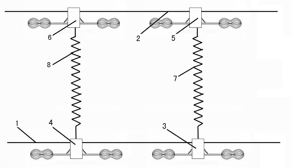
[0019] Such as figure 1 As shown, the device for preventing wire vibration in all directions of the present invention has a specific structure as follows: the first wire 1 and the second wire 2 are arranged in parallel in the horizontal direction, and a first anti-vibration hammer 3 and a second anti-vibration hammer are installed on the first wire 1 . Hammer 4, the third anti-vibration hammer 5 and the fourth anti-vibration hammer 6 are installed on the second wire 2, the first shock-absorbing spring 7 is arranged between the first anti-vibration hammer 3 and the ...


PUM


Abstract

The invention discloses an oscillating preventing device for a guide line, and in particular relates to a device for comprehensively preventing the guide line from oscillating. The device for comprehensively preventing the guide line from oscillating is characterized in that a first guide line and a second guide line are arranged in parallel in the horizontal direction; a first oscillating preventing hammer and a second oscillating preventing hammer are mounted on the first guide line; a third oscillating preventing hammer and a fourth oscillating preventing hammer are mounted on the second guide line; a first damping spring is arranged between the first oscillating preventing hammer and the third oscillating preventing hammer; a second damping spring, which has the same length and structure as the second damping spring, is arranged between the second oscillating preventing hammer and the fourth oscillating preventing hammer; the distance from a wire clamp plate of the first oscillating preventing hammer to the wire clamp plate of the second oscillating preventing hammer is equal to the length of the first damping spring; the distance from the third oscillating preventing hammer to the fourth oscillating preventing hammer is equal to the length of the second damping spring, The device has a good effect on preventing the guide line from guiding and shaking, is long in service life, and solves the influence of an additional vibrating bending stress of the oscillating preventing device on the guide line, and thus the service life of the guide line is prolonged.

Description

technical field [0001] The invention relates to an anti-vibration device for wires, in particular to a device for preventing wires from vibrating in all directions. Background technique [0002] The overhead transmission wire is affected by wind, ice, low temperature and other meteorological conditions, causing the line to vibrate and dance. The vibration frequency is high and the amplitude is small. The wind vibration causes the overhead line to be repeatedly bent at the suspension point, causing material fatigue, and finally leads to broken strands and broken lines. The frequency of galloping is very low, but the amplitude is very large, which can easily cause phase-to-phase flashover, resulting in serious accidents such as line tripping, power failure or burning of wires. In order to solve the above-mentioned problem of wire vibration, the usual solution is to hang an anti-vibration hammer on the high-voltage overhead line wire. When the overhead line vibrates, the ant...

Claims


Application Information

Patent Timeline
Patent Type & Authority Applications(China)
IPC IPC(8): H02G7/14
Inventor 郝辉王孟男于浩卜新良王立辉罗文光张戬
Owner FUXIN POWER SUPPLY COMPANY STATE GRID LIAONING ELECTRIC POWER
Why Eureka
Try Eureka