
Swinging device for welding machine

A technology of swinging device and sliding device, which is applied in the direction of auxiliary devices, welding equipment, welding equipment, etc., can solve the problems that the welding machine cannot swing, adjust the angle, etc., and achieve the effect of expanding the application field

Inactive Publication Date: 2014-12-31
SHANGHAI ZHONGZHOU SPECIAL ALLOY MATERIALS
View PDF7 Cites 0 Cited by
  • Summary
  • Abstract
  • Description
  • Claims
  • Application Information

AI Technical Summary

Problems solved by technology

[0003] The technical problem to be solved by the present invention is to provide a swing device for welding machines in order to overcome the defect that the existing welding machines cannot swing and then adjust the angle

Method used


Image

  • Swinging device for welding machine

Examples


Embodiment

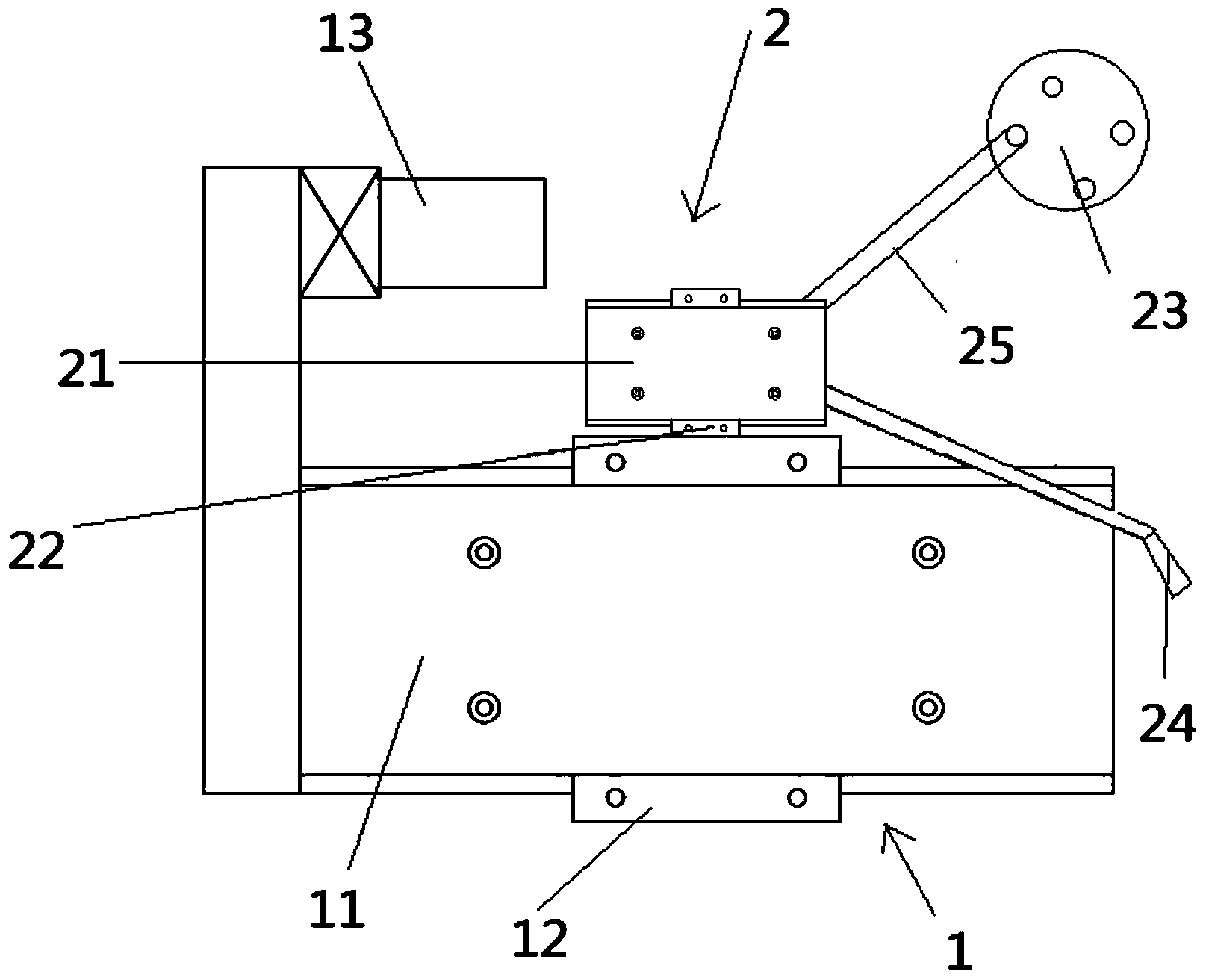
[0028] Please combine figure 1 It should be understood that a swing device for a welding machine includes: a base sliding device 1, a welding torch sliding device 2, the base sliding device 1 includes a base body 11 and a base sliding part 12 fixed to the base body 11, the base sliding part 12 (can be a slide block with rollers at the bottom) cooperate with the base slide rail fixed on the platform, the welding torch sliding device 2 includes a welding torch base body 21, a welding torch base sliding part 22, and an eccentric wheel 23, and the upper part of the base sliding device 1 has The welding torch slide rail matched with the welding torch base sliding part 22, one end of the welding torch base body 21 is connected with the eccentric wheel 23 by a belt 25, and the eccentric wheel 23 is fixed on the platform and will not move with the swing device. The welding torch slide rail and the base slide rail are perpendicular to each other, which enables the base sliding device 1...


PUM


Abstract

The invention provides a swinging device for a welding machine. The swinging device comprises a base sliding device and a welding gun sliding device; the base sliding device comprises a base body and a base sliding part fixed onto the base body, and the base sliding part is matched with a base slide rail fixed onto a platform; the welding gun sliding device comprises a welding gun base body, a welding gun base sliding part and an eccentric wheel; the upper portion of the base sliding device is provided with a welding gun slide rail matched with the welding gun base sliding part, and one end of the welding gun base body is connected with the eccentric wheel. The swinging device for the welding machine has the advantage that multi-angle welding of welded products can be realized to provide higher-quality welded products.

Description

technical field [0001] The invention relates to an oscillating device, in particular to an oscillating device for a welding machine. Background technique [0002] CMT (Cold Metal Transfer, cold metal transfer) welding technology is a spatter-free, high-efficiency, low-heat emerging welding method. Using this welding method, special materials can be coated and welded on the surface of products (such as V-shaped spheres). Therefore, it can Extend the life of the product. However, if the welding material with poor fluidity is encountered, it is not easy to spread during welding, and the welding machine usually does not have a swing device, and the surface of the product cannot be welded at multiple angles by increasing the swing, which brings great benefits to the wide application of CMT welding technology. coming restrictions. Contents of the invention [0003] The technical problem to be solved by the present invention is to provide a swing device for a welder in order to...

Claims


Application Information

Patent Timeline
Patent Type & Authority Applications(China)
IPC IPC(8): B23K37/02B23K9/00
CPCB23K37/0229B23K37/0252
Inventor 于建平赵爱东余年春倪涛
Owner SHANGHAI ZHONGZHOU SPECIAL ALLOY MATERIALS
Learn More