Multi-angle swing type automatic welding machine for electrical engineering

An automatic welding machine and electrical engineering technology, applied in welding equipment, auxiliary welding equipment, welding/cutting auxiliary equipment, etc., can solve the problems of insufficient welding accuracy of workpieces, time-consuming and laborious, and improve welding efficiency and accuracy. The effect of clamping and simple structure

Inactive Publication Date: 2022-02-11
YANGZHOU POLYTECHNIC INST
View PDF0 Cites 0 Cited by
  • Summary
  • Abstract
  • Description
  • Claims
  • Application Information

AI Technical Summary

Problems solved by technology

[0002] For the welding process of the workpiece, in order to take into account its performance and welding firmness, multi-directional welding of the workpiece is required; although most of the existing welding machines can effectively realize automatic welding, it is still difficult to realize multi-directional welding of the workpiece based on the same machine , so in the existing operation, after completing the welding of one orientation of the workpiece, it is necessary to manually switch the orientation of the workpiece and re-clamp it, which is time-consuming and laborious, and easily leads to insufficient welding accuracy of the workpiece

Method used


Image

  • Multi-angle swing type automatic welding machine for electrical engineering
  • Multi-angle swing type automatic welding machine for electrical engineering
  • Multi-angle swing type automatic welding machine for electrical engineering

Examples


Embodiment approach 1

[0059] In the first embodiment, the Z-axis rising assembly 2 includes:

[0060] The first outer lever 201;

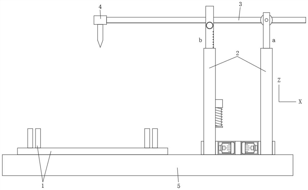
[0061] The electric lifting rod 202 is disposed inside the first outer lever 201, the top of the electric lifting rod 202 through the first outer lever 201, and the cross-frame 3 penetrates the telescopic end fitted to the electric lifting rod 202.

[0062] From the above, in the first embodiment, automatic lifting is achieved by the driving of the electric rod 202.

Embodiment approach 2

[0063] In the second embodiment, the Z-axis rising and lower assembly 2 includes:

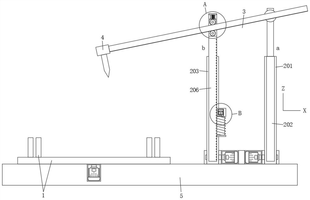
[0064] The second outer lever 203; there is a mounting groove on one side of the second outer lever 203, and two mount 204 is fixed to the mounting groove symmetry, and one of the mount 204 is provided with a rotating motor in two mount 204. A threaded rod 205 that can be rotated around the Y axis is connected between the thread, and the threaded rod 205 is rotated by rotating the motor;

[0065] The lifting inner rod 206 is slidably in the second outer lever 203 along the Z axis, and a threaded groove is opened on one side of the lifting inner rod 206, and the threaded rod 205 is spiiled to the lifting inner rod 206 through the threaded groove.

[0066] From the above, in the second embodiment, the thread rod 205 is generated between the thread rod 205 and the rod 205 and the lifting inner rod 206, thereby effectively driving the lifting inner rod 206 moves along the Z axis, and effectively realiz...


PUM


Abstract

The invention belongs to the technical field of automatic welding equipment, and discloses a multi-angle swing type automatic welding machine for electrical engineering, wherein the automatic welding machine comprises a fixing device for clamping a workpiece, two Z-axis lifting assemblies, a transverse frame and a welding head; the two Z-axis lifting assemblies are arranged in parallel along the X axis, the Z-axis lifting assemblies are located on one side of the fixing device, and the bottoms of the Z-axis lifting assemblies can rotate around the X axis by 180 degrees; the transverse frame sequentially penetrates through the two Z-axis lifting assemblies along the X axis, is close to the tops of the Z-axis lifting assemblies and can rotate around the Y axis on the Z-axis lifting assemblies; and the welding head is fixed at one end of the transverse frame and is used for carrying out multi-angle welding on a workpiece clamped on the fixing device. In conclusion, on the basis of cooperation of the Z-axis lifting assemblies and the transverse frame, the welding machine can conveniently adjust the positioning position and the welding direction of the welding head according to different welding directions, then automatic multi-angle welding is effectively achieved, and the welding efficiency and accuracy are improved.

Description

Technical field [0001] The present invention belongs to the technical field of automatic welding equipment, and more particularly to a multi-angle swing type automatic welding machine for electrical engineering. Background technique [0002] For the welding processing of the workpiece, it is necessary to take care of its performance and welding firmness, it is necessary to carry out the workpiece multi-directional welding; the existing welding machine can most effectively achieve automated welding, but it is still difficult to achieve multi-directional welding of workpieces based on the same machine. Therefore, in the existing operation, after the workpiece is stored, the workpiece is required to manually switch the workpiece or re-hold, and the time is laborious, and the workpiece is not short-term. Inventive content [0003] In view of this, in order to solve the problems presented in the above background, it is an object of the present invention to provide a multi-angle swing...

Claims


Application Information

Patent Timeline
Patent Type & Authority Applications(China)
IPC IPC(8): B23K37/02B23K37/04
CPCB23K37/0252B23K37/0435
Inventor 李红春
Owner YANGZHOU POLYTECHNIC INST
Why Eureka
Try Eureka