
Mobile robot

a mobile robot and robot technology, applied in the field of mobile robots, can solve the problems of limited range of motion, limited flexibility in the utility of the first link, and limited flexibility of the prior art mobile robots

Active Publication Date: 2013-01-29
CHINA SUPERROBOTICS LTD
View PDF19 Cites 38 Cited by
  • Summary
  • Abstract
  • Description
  • Claims
  • Application Information

AI Technical Summary

Benefits of technology

[0006]Accordingly the present invention would be advantageous to provide a mobile robot with a dual purpose manipulation arm that is attached to the chassis of the robot by way of a turret. Thereby the manipulation arm may be deployed to the sides of the robot as well to the front and the back. As well, the manipulator arm is adapted to be used to increase the wheel or track base, as well as for other functions. The mobile robot of the present invention has the ability to lift its front pulleys or wheels forward and upward thus increasing it ability to ascend and descend stairs and to manoeuvring around obstacles. As well, the mobile robot of the present invention can adjust the position of its centre of gravity to protect it turning over while ascending and descending stairs and manoeuvring around obstacles.

Problems solved by technology

One of the big challenges in regard to mobile robots is manoeuvring them up and down stairs, over obstacles and uneven terrains.
With regard to all of these prior art mobile robots their versatility is limited because the first link is pivotally attached to the platform or chassis with only one degree of freedom.
Accordingly the range of motion is limited and the flexibility in the utility of the first link is limited.
However, this sliding friction will cause a reduced working efficiency and possible failure due to the arm / link wear-out.

Method used


Image

  • Mobile robot
  • Mobile robot
  • Mobile robot

Examples


Embodiment Construction

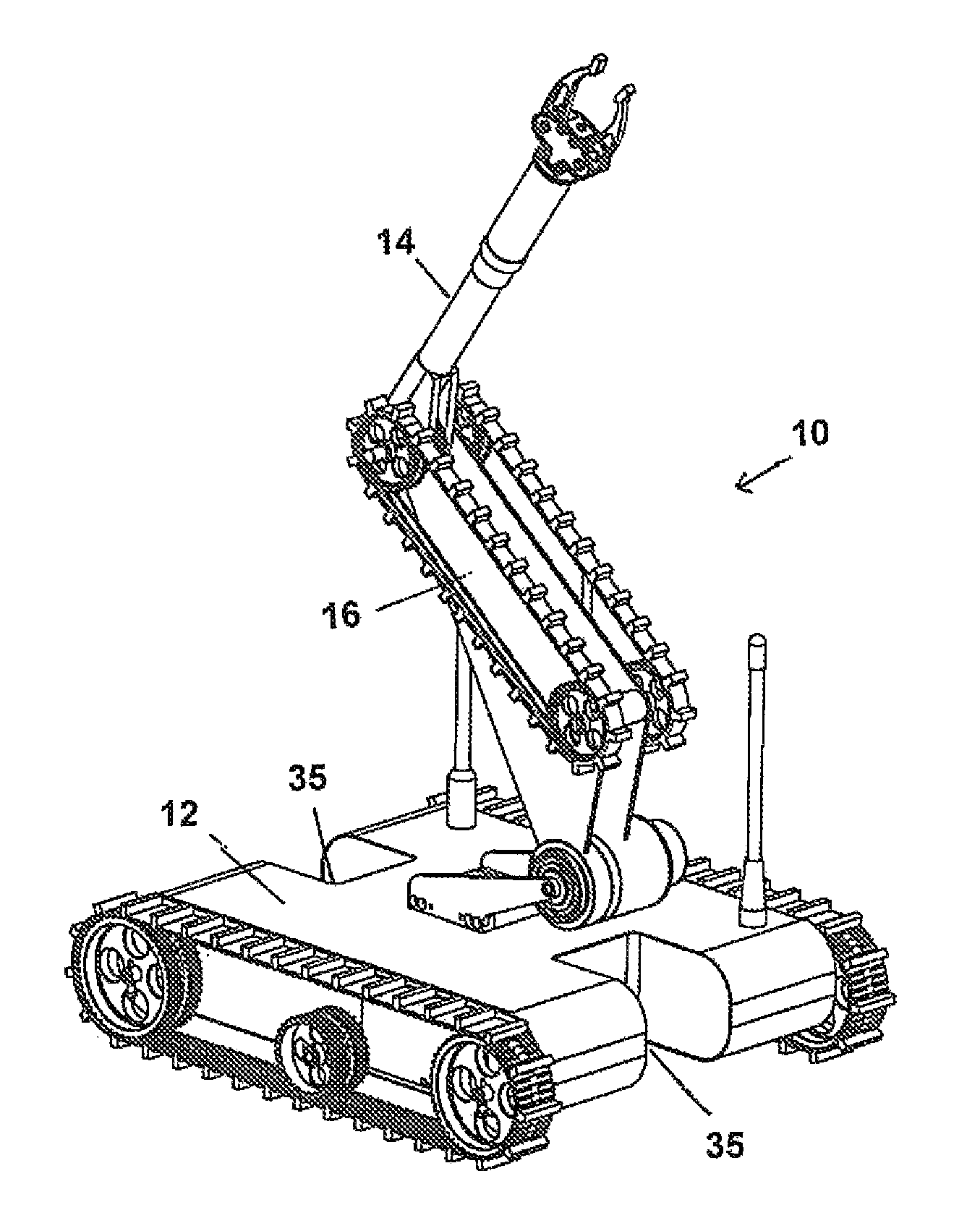
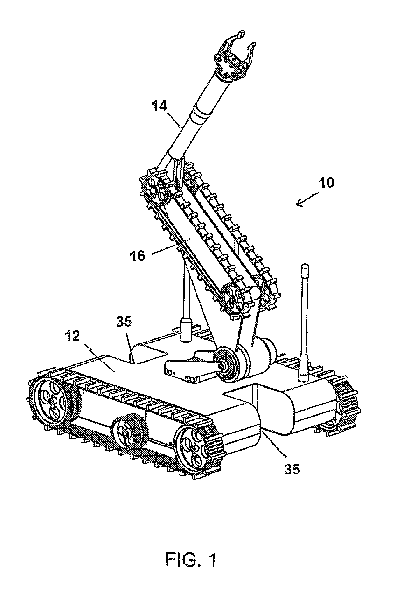
[0045]Referring to FIG. 1, the mobile robot 10 is a novel mobile robot that has been designed based on the combination of a mobile platform 12 and a manipulation arm 14. The core concept is that the first link or shoulder link 16 of the manipulator arm is not only a part of the arm, but also it can be used as an aid in mobility of the platform to enhance the robot's capability in regard to climbing stairs and overcoming obstacles.

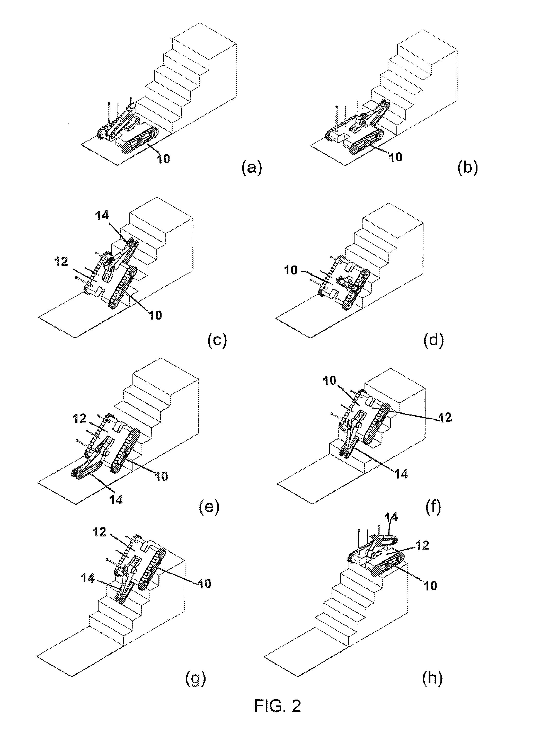
[0046]FIG. 2(a) to (h) shows how the first link 16 of the mobile robot 10 may be used to aid in climbing stairs. FIG. 3(a) to (h) shows how the first link 16 of the mobile robot 10 may be used to crossing ditches.

[0047]Referring to FIGS. 4 to 7, the platform 12 has a chassis or frame 18. A pair of drive systems is attached opposed sides of the chassis 18. In one embodiment the drive systems are track and pulley systems that are attached to each side of the chassis 18. Each track 20 and pulley system includes a track 20, a pair of drive pulleys 22 at either ...


PUM


Abstract

The mobile robot includes a chassis, a pair of drive system, a manipulator arm with a turret. The pair of drive systems is operably connected to opposed sides of the chassis. The turret is rotationally attached to the platform. The first link of the manipulator arm is attached to the turret at a first joint. The manipulator arm has at least a first link, and the first link is adapted to function as a traction device.

Description

CROSS REFERENCE TO RELATED PATENT APPLICATION[0001]This patent application relates to U.S. Provisional Patent Application Ser. No. 61 / 295,113 filed on Jan. 14, 2010 entitled MOBILE ROBOT which is incorporated herein by reference in its entirety.FIELD OF THE INVENTION[0002]This invention relates to mobile robots and in particular to mobile robots that includes a linkage mechanism with a dual function.BACKGROUND OF THE INVENTION[0003]The present invention relates to mobile robots. Mobile robots are typically designed to be either remotely controlled or are autonomous. One of the big challenges in regard to mobile robots is manoeuvring them up and down stairs, over obstacles and uneven terrains.[0004]It is known to those skilled in the art that by extending the wheel base or track base the ability of the mobile robot to manoeuvre stairs and overcome obstacles can be enhanced. There have been some devices that have been suggested which attempt to extend the wheel or track base. Specific...

Claims


Application Information

Patent Timeline
Patent Type & Authority Patents(United States)
IPC IPC(8): B62D55/075
CPCB25J5/005B62D57/024B62D55/075Y10T74/20305
Inventor GOLDENBERG, ANDREW A.LIN, JUN
Owner CHINA SUPERROBOTICS LTD
Learn More