Replacement stock system for rifle

Inactive Publication Date: 2015-01-13
VINCENT JEFF +1
View PDF30 Cites 32 Cited by
  • Summary
  • Abstract
  • Description
  • Claims
  • Application Information

AI Technical Summary

Benefits of technology

[0012]The firing control mechanism may include a primary safety lever that captures the original trigger safety tab, which may be a part of the original trigger group. This lever may be rotated toward the rear to disable the original trigger group or forward to enable actuation of the original trigger group. Used in combination with the safety spool and trigger rod described herein, the firearm can be made fully safe. Without this element of the firing control mechanism, the rifle may remain capable of unintended discharge, thus creating a potentially significant safety risk.
[0013]For pu

Problems solved by technology

The variety of weapons and ammunition was inefficient and as such, a replacement weapon for all four of the above mentioned weapons was developed.
The smaller 5.56 mm M16 round not only lacked in the range of the M14, but also lacked stopping power compared to t

Method used


Image

  • Replacement stock system for rifle
  • Replacement stock system for rifle
  • Replacement stock system for rifle

Examples


Example

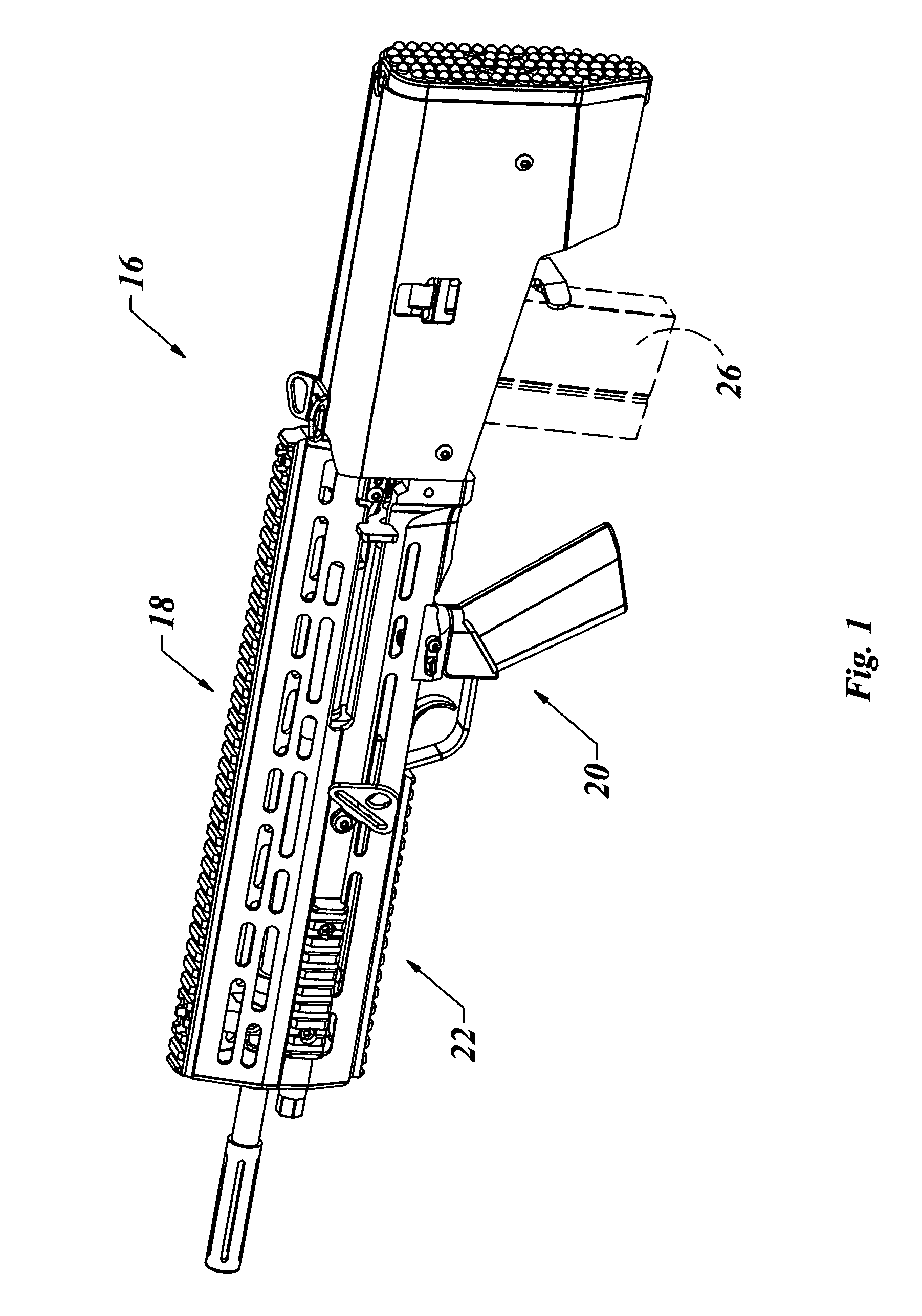
[0030]With reference to the illustrative drawings, and particularly to FIGS. 1-4, there is shown a rifle assembly 16 including a replacement stock system in accordance with the present invention. The rifle assembly 16 may include an upper rail assembly 18, a trigger assembly group 20 and a stock assembly 22, including a cheek panel 24 and a magazine 26, though the magazine 26 is not considered part of the invention and is shown only for illustrative purposes. In FIG. 1, the rifle assembly 16 is shown in an assembled state.

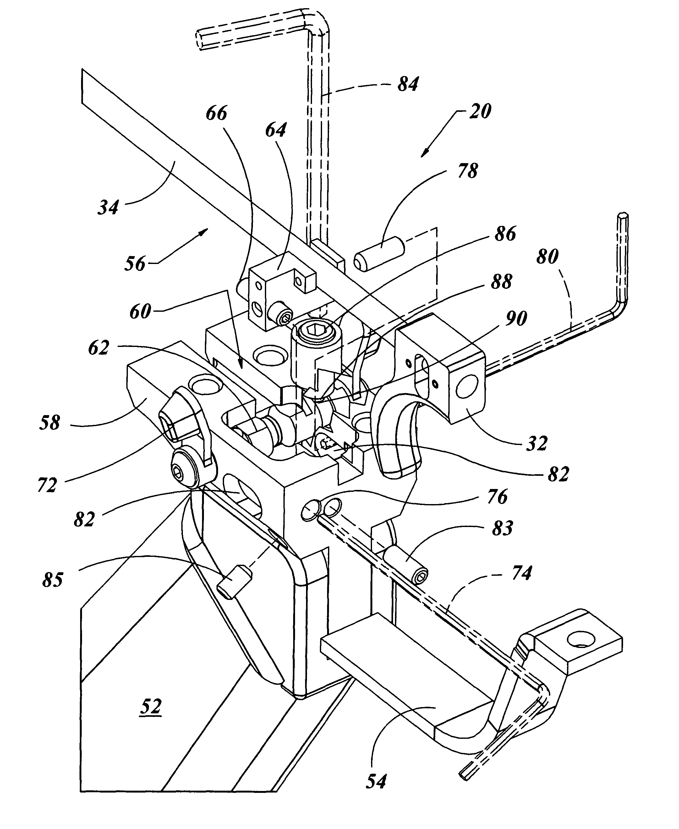
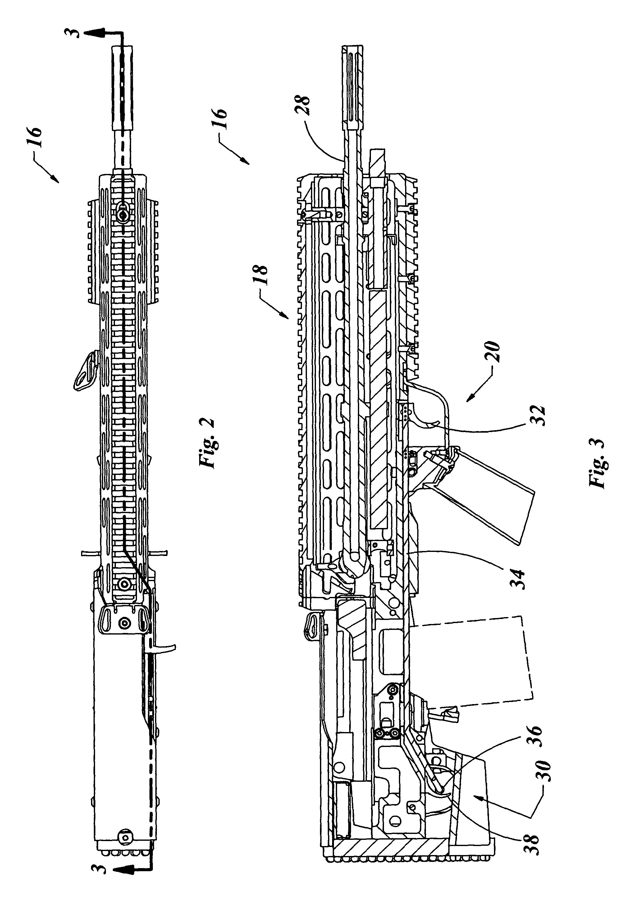
[0031]With reference to FIG. 2, the rifle assembly 16, as shown in FIG. 1 from a top view with section line 3-3 shows the location of the section, as shown in FIG. 3. The section shown in FIG. 3 illustrates the interaction of the some parts of an existing rifle assembly 16, such as, some elements of the upper rail assembly 18, including the barrel 28, and the primary trigger group 30 which may work with other elements of the rifle assembly 16, including the trigger...


PUM


Abstract

A trigger assembly group of the type used with a rifle stock replacement system is provided. The trigger assembly group and may include a trigger assembly, including a trigger coupled to a trigger rod, a locking plate coupled to the trigger rod and a preload cylinder coupled to the locking plate. This in combination with the firing elements of the existing rifle may comprise a firing control mechanism. The trigger assembly group may also include a trigger block with a recess adapted to receive the trigger rod and the locking plate. A safety spool may be a part of the trigger assembly group and include a cross hole, which may be adapted to receive the preload cylinder when the safety spool is in a first position and not receive the preload cylinder when the safety spool is in a second position.

Description

CROSS-REFERENCE TO RELATED APPLICATION DATA[0001]Priority is claimed under 35 U.S.C. §119(e) to U.S. Provisional Application No. 61 / 634,102, filed on Feb. 23, 2012, which is incorporated by reference herein.FIELD OF THE INVENTION[0002]The present invention generally relates to firearm modification packages and, more particularly, replacement stock systems including safety mechanisms for firearms.BACKGROUND OF THE INVENTION[0003]In the 1940's, after WWII, the US Military desired a replacement rifle for the M-1, the Browning Automatic Rifle, the Carbine and the M3 A-1 Sub-machine gun. In many cases a squad would be carrying each of these four weapons in battle. The variety of weapons and ammunition was inefficient and as such, a replacement weapon for all four of the above mentioned weapons was developed. This weapon was the U.S. Rifle M14.[0004]The M-14 uses a standard 7.62 mm×51 NATO round and may be fired semiautomatic (one round fired with each trigger pull), or full automatic (co...

Claims


Application Information

Patent Timeline
IPC IPC(8): F41A17/46F41A19/10
CPCF41A17/46F41A19/10
Inventor VINCENT, JEFFVENTURI, ROGER
Owner VINCENT JEFF
Why Eureka
Try Eureka