

Head mounted display and optical position adjustment method of the same
a technology of optical position adjustment and display, which is applied in the direction of instruments, static indicating devices, optical elements, etc., can solve the problems of viewer fatigue and difficulty in adjustmen
Active Publication Date: 2014-11-27
SONY CORP
View PDF4 Cites 35 Cited by
- Summary
- Abstract
- Description
- Claims
- Application Information
AI Technical Summary
Benefits of technology
The present invention provides methods for adjusting the position of two images on a head mounted display by controlling the first image signal. This allows for easy optical adjustment of the two image display devices during manufacture and reduces the need for special parts or mechanical adjustment. The mutual optical positions of the two image display devices can be adjusted without using any special parts or mechanical adjustment, thus reducing manufacturing steps, cost, and adjustment time. Additionally, the viewer can actively or passively change the distance to the virtual image formed by the two optical devices, allowing for comfortable viewing and reducing discomfort when wearing the head mounted display. Overall, the invention provides improved methods for adjusting the positions of two images on a head mounted display.
Problems solved by technology
This leads to discrepancy in preadjusted spatial distance to the virtual image, causing fatigue to the viewer during viewing.
However, such an adjustment is often difficult to achieve.
Method used
View moreImage
Smart ImageViewing Examples

Examples
example 2 (modification of example 1)
3. Example 2 (modification of example 1)
4. Example 3 (another modification of example 1)
example 4 (modification of example 3)
5. Example 4 (modification of example 3)
6. Example 5 (modification of examples 1 to 4)
example 6 (modification of example 5)
7. Example 6 (modification of example 5)
8. Example 7 (still another modification of example 1)
9. Example 8 (optical position adjustment method of the head mounted displays according to the second and fourth embodiments)
Login to View More PUM
 Abstract
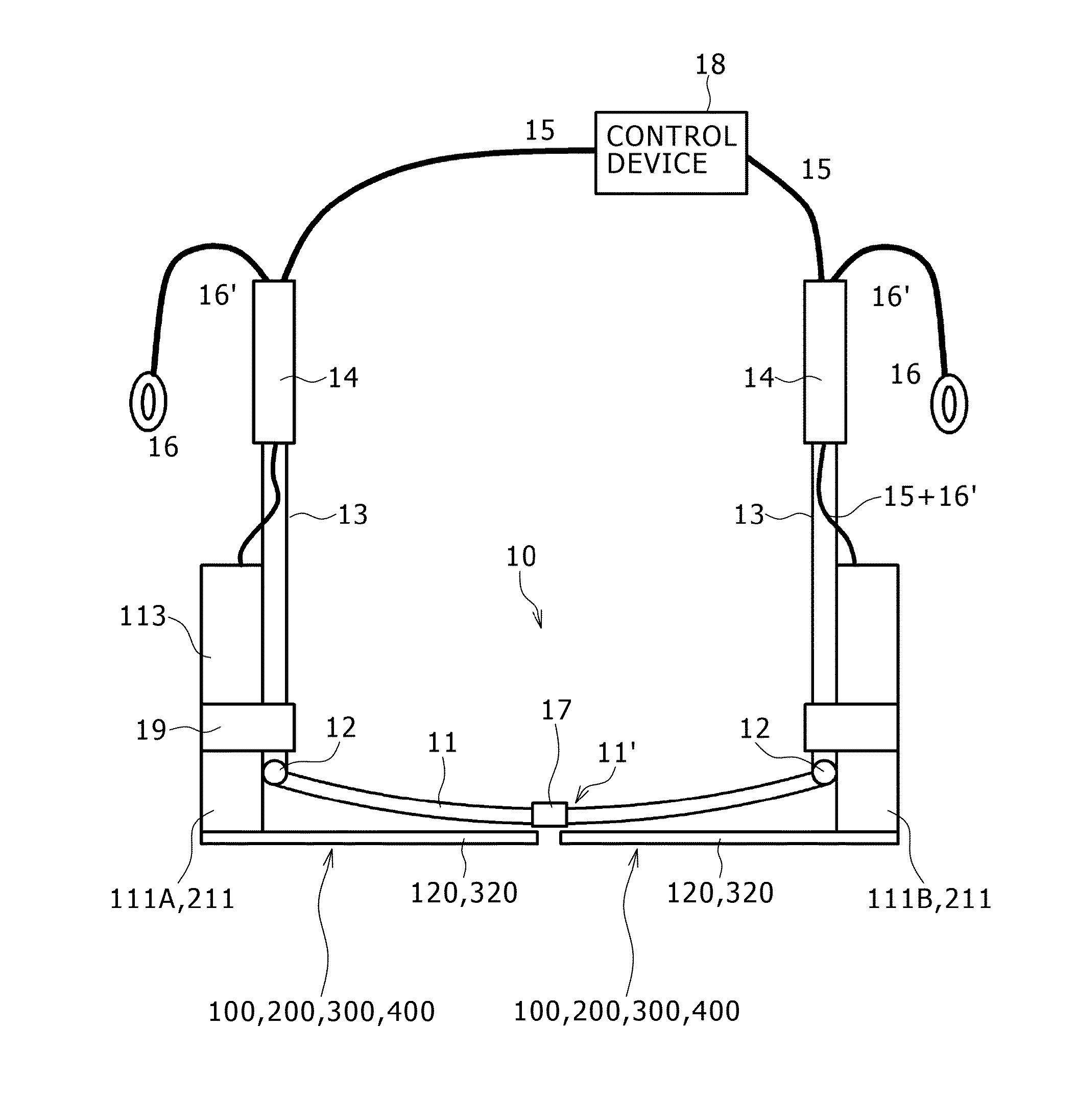
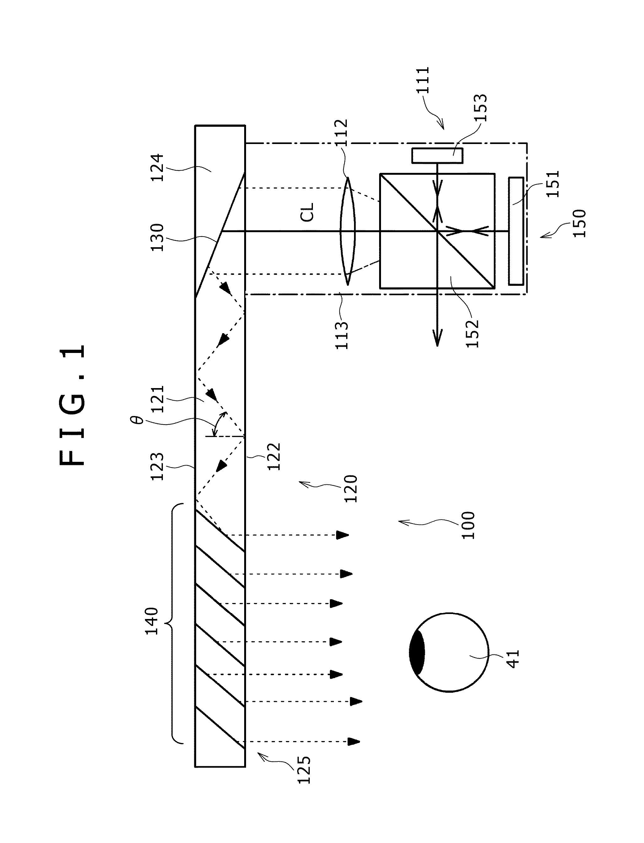
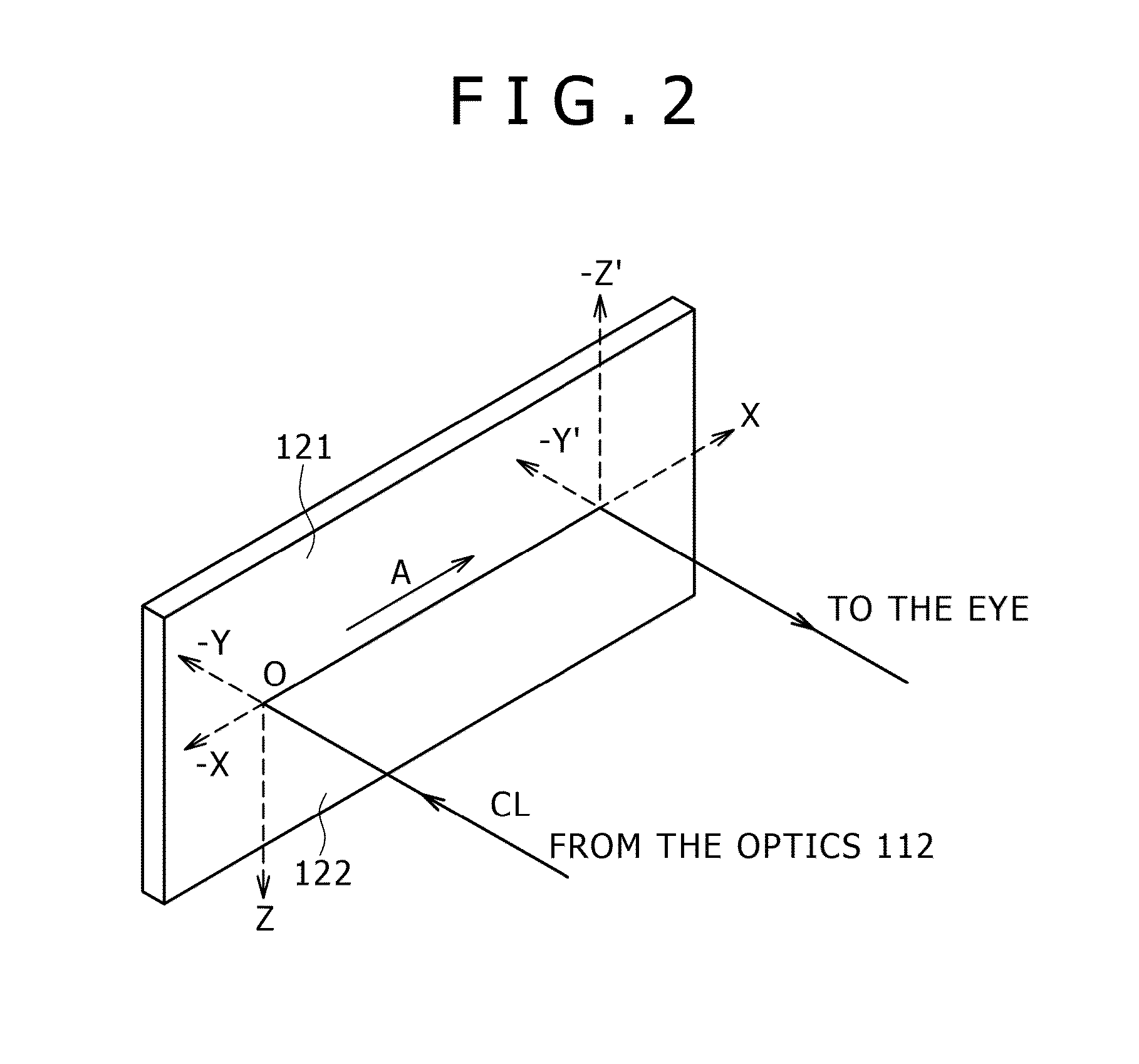
Disclosed herein is an optical position adjustment method of a head mounted display, the head mounted display including (a) an eyeglass type frame worn on the head of a viewer, and (b) two image display devices for the right and left eyes attached to the frame, and each of the image display devices including (A) an image forming device, and (B) an optical device adapted to receive, guide and emit light emitted from the image forming device, wherein the optical position adjustment method includes the step of: controlling an image signal that is supplied to the image forming device making up at least one of the image display devices so as to control the position of the image displayed on the optical device making up at least one of the image display devices and adjust the mutual positions of the two images.
Description
CROSS REFERENCES TO RELATED APPLICATIONS[0001]This application is a continuation of U.S. patent application Ser. No. 13 / 078,147, entitled “HEAD MOUNTED DISPLAY AND OPTICAL POSITION ADJUSTMENT METHOD OF THE SAME,” filed on Apr. 1, 2011, which claims the benefit under 35 U.S.C. §119 of the filing date of Japanese Patent Application JP 2010-089494, filed on Apr. 8, 2010. Each of the foregoing documents is incorporated by reference in its entirety.BACKGROUND OF THE INVENTION[0002]1. Field of the Invention[0003]The present invention relates to a head mounted display (HMD) and an optical position adjustment method of the head mounted display.[0004]2. Description of the Related Art[0005]A virtual image display device (image display device) is well known, for example, from Japanese Patent Laid-Open No. 2006-162767 that is designed to allow for the viewer to view a two-dimensional image, formed by an image forming device, as an enlarged virtual image by means of a virtual image optics.[0006]...
Claims
Login to View More Application Information
Patent Timeline
 Patent Type & AuthorityApplications(United States)
IPC IPC(8): G06F3/01
CPCG06F3/012G02B2027/0134G02B2027/0138G02B2027/0161G02B2027/014G06F3/1423G09G3/002G09G3/003G09G2340/0464G09G2354/00G09G2356/00G02B27/017H04N13/344H04N13/398G02B27/0172G02B2027/0178G06T19/006G02B27/0103G02B2027/0109G02B2027/0174
InventorMIYAWAKI, TETSUYUKIMATSUMURA, IKUO
OwnerSONY CORP