
A fluid continuous sedimentation reactor for removing iron and impurities

A reactor and continuous technology, applied in chemical instruments and methods, water/sewage multi-stage treatment, water/sludge/sewage treatment, etc., can solve the problems of incomplete removal of impurities, long-term action time, difficult operation, etc. Achieve fast and efficient iron and impurity removal, short action time, and small footprint

Active Publication Date: 2019-02-22
CHANGSHA HASKY ENVIRONMENTAL PROTECTION TECH DEV CO LTD
View PDF6 Cites 0 Cited by
  • Summary
  • Abstract
  • Description
  • Claims
  • Application Information

AI Technical Summary

Problems solved by technology

[0002] Existing fluid iron removal devices generally use gravity to flow through the iron removal device to achieve the effect of iron removal. Since the flow direction is generally from top to bottom, and the flow speed is fast, the eddy current of the fluid can easily remove the ferromagnetic material. Substances are involved in the fluid again, which affects the efficiency of iron removal. At the same time, after a certain amount of ferromagnetic substances are absorbed by the magnetic field, cleaning operations are required, which cannot meet the requirements of continuous generation. At the same time, the structure of the device is complicated and the operation is difficult. Meet the requirements of fully automatic control
At the same time, considering that the existing fluid sedimentation and impurity removal devices often only use the gravity effect for sedimentation, the required action time is long, the required area is large, and the impurity removal effect is not thorough

Method used


Image

  • A fluid continuous sedimentation reactor for removing iron and impurities

Examples


Embodiment 1

[0031] Use this reactor to process Fe 3+ The copper sulfate leaching solution with a content of 6.67g / L, after the leaching solution is added with medicines to adjust the slurry, is connected to the continuous sedimentation reactor for iron and impurity removal of this fluid for sedimentation. After the above treatment, the precipitate quickly settled within one minute, the precipitate was easy to filter, and the Fe in the supernatant 3+ down to 2.95mg / L.

Embodiment 2

[0033] Use this reactor to process Fe3+ The copper sulfate leaching solution with a content of 13.4g / L, after the leaching solution is added with medicines to adjust the slurry, is connected to the continuous sedimentation reactor for iron and impurity removal of this fluid for sedimentation. After the above treatment, the precipitate quickly settled within five minutes, the precipitate was easy to filter, and the Fe in the supernatant 3+ down to 3.15mg / L.

Embodiment 3

[0035] Use this reactor to process Fe 3+ The zinc sulfate solution with a content of 5.8g / L, after the leaching solution is added with drugs to adjust the slurry, is connected to this fluid continuous sedimentation reactor for iron and impurity removal for sedimentation. After the above treatment, the precipitate quickly settled within one minute, the precipitate was easy to filter, and the Fe in the supernatant 3+ down to 2.16mg / L.


PUM


Abstract

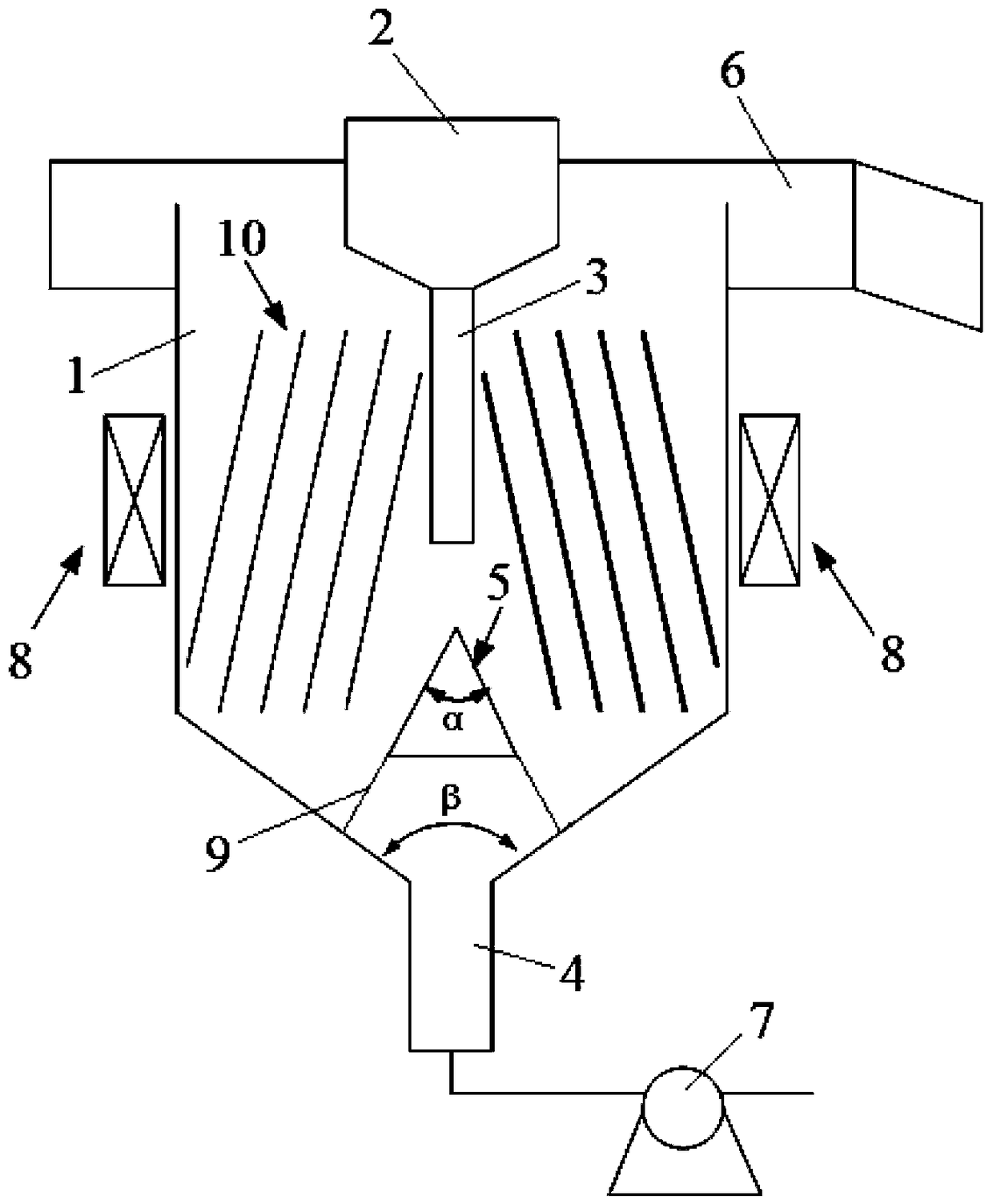
The invention discloses a fluid continuous-settlement iron-removal impurity-removal reactor. The fluid continuous-settlement iron-removal impurity-removal reactor is characterized by comprising a feeding trough, a cone-bottom reactor cylindrical-shell, a discharge gate, a feeding extension pipe connected to the bottom of the feeding trough, a base cone located in the cone-bottom reactor cylindrical-shell, an overflow groove located at the top of the cone-bottom reactor, a discharge mechanism located at the discharge gate, and a mechanism for supplying an internal pulse magnetic field for the cone-bottom reactor cylindrical-shell. The device above the feeding trough and the device at the outlet of the discharge gate are provided with valves, the bottom of the cone-bottom reactor is provided with a cleaning device, a peristaltic pump is used for dreg discharge at the discharge gate, a bed charge collection tank is arranged at an outlet of the peristaltic pump, and the outlet of the overflow groove is provided with an overflow connection pipe connected to other devices. Compared with the existing fluid iron and impurity removal device, the fluid continuous-settlement iron-removal impurity-removal reactor utilizes combination of advantages of gravity settlement and magnetic force settlement, has thorough iron and impurity-removal effects, realizes continuous iron and impurity removal and material discharge and reduces the influence produced by fluid flowing on iron and impurity removal effects.

Description

technical field [0001] The invention relates to a fluid continuous sedimentation reactor for removing iron and impurities. Background technique [0002] Existing fluid iron removal devices generally use gravity to flow through the iron removal device to achieve the effect of iron removal. Since the flow direction is generally from top to bottom, and the flow speed is fast, the eddy current of the fluid can easily remove the ferromagnetic material. Substances are involved in the fluid again, which affects the efficiency of iron removal. At the same time, after a certain amount of ferromagnetic substances are absorbed by the magnetic field, cleaning operations are required, which cannot meet the requirements of continuous generation. At the same time, the structure of the device is complicated and the operation is difficult. Meet the requirements of fully automatic control. At the same time, it is considered comprehensively that in the existing fluid sedimentation and impurit...

Claims


Application Information

Patent Timeline
Patent Type & Authority Patents(China)
IPC IPC(8): C02F9/12C02F101/20
Inventor 孙伟唐鸿鹄刘文莉韩海生
Owner CHANGSHA HASKY ENVIRONMENTAL PROTECTION TECH DEV CO LTD
Learn More