A magnetostrictive guided wave transducer

A magnetostrictive and transducer technology, applied in the direction of material magnetic variables, etc., can solve the problems of low detection efficiency, inconvenient disassembly and assembly, and complicated steps, and achieve the effects of high detection efficiency, convenient disassembly and assembly, and a wide range of applications.

Active Publication Date: 2022-04-01
WUHAN HUAYUYIMU TESTING EQUIP CO LTD
View PDF7 Cites 0 Cited by
  • Summary
  • Abstract
  • Description
  • Claims
  • Application Information

AI Technical Summary

Problems solved by technology

However, since the magnetic field direction of the permanent magnet of the yoke-type magnetizer is perpendicular to the surface of the test piece, the adsorption force is very large, and it is inconvenient to disassemble, and every time the transducer is disassembled, the magnetizer must be disassembled first, and then the coil is disassembled. The steps are cumbersome. Low detection efficiency
In addition, for some tubular, rod-shaped and other components with only part of the outer surface exposed, the full-circle coil will no longer be applicable.

Method used


Image

  • A magnetostrictive guided wave transducer
  • A magnetostrictive guided wave transducer
  • A magnetostrictive guided wave transducer

Examples


Embodiment 1

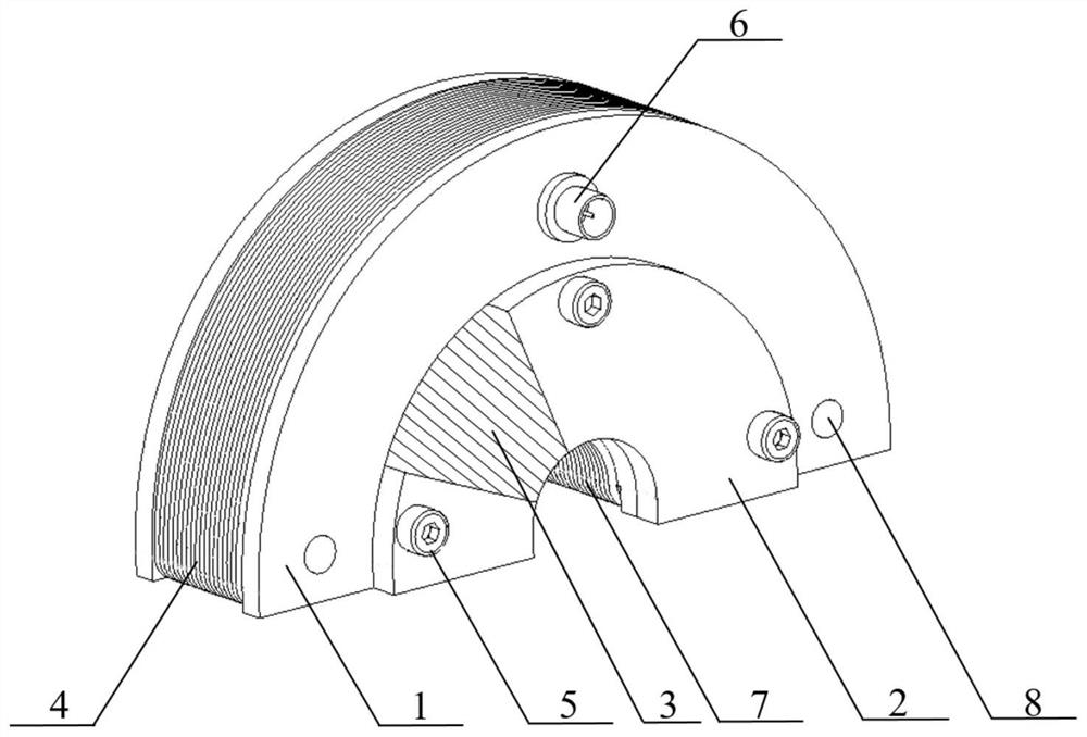
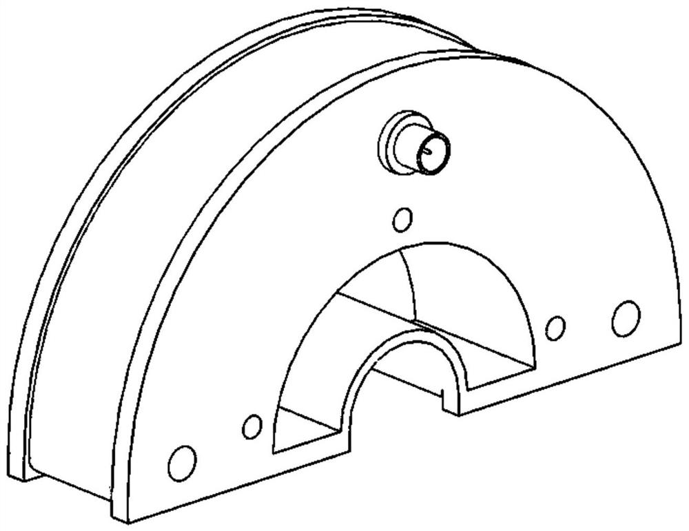
[0043] The component 10 to be tested is a steel pipe made of No. 20 steel, with an outer diameter of 20 mm, a wall thickness of 1 mm, and a length of 2500 mm. Both the transducer at the excitation end and the transducer at the receiving end use semi-cylindrical magnetostrictive guided-wave transducers, and the skeleton 1 and protective shell 2 of the semi-cylindrical magnetostrictive guided-wave transducer are made of photosensitive resin , the thickness is 30mm, the diameter of the outermost large circle of skeleton 1 is 122mm, the diameter of the innermost small circle is 24mm, the inner diameter of the protective shell is 24mm, the outer diameter is 68mm, and the thickness is 5mm; Composed of magnets, the permanent magnet 3 has an inner diameter of 28mm, an outer diameter of 58mm, and a thickness of 30mm. The magnetization direction is as follows: Figure 5As shown; the inner solenoid coil 7 is wound by an enameled wire with a wire diameter of 1.08 mm, the number of turns i...

Embodiment 2

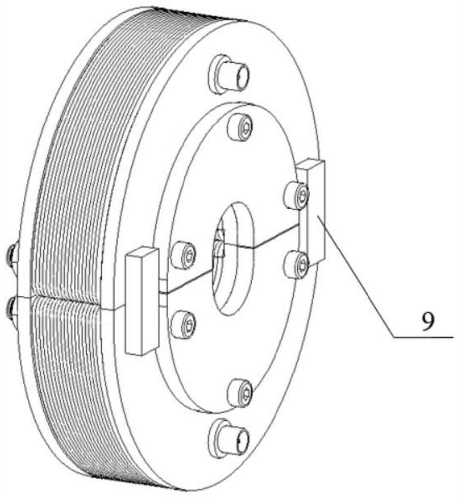
[0046] Both the transducer at the excitation end and the transducer at the receiving end use cylindrical magnetostrictive guided wave transducers, and each cylindrical magnetostrictive guided wave transducer consists of two semi-cylindrical magnetostrictive guided wave transducers Assembled, the parameters of the semi-cylindrical magnetostrictive guided wave transducer and the member to be tested 10 are the same as those in Embodiment 1.

[0047] The cylindrical magnetostrictive guided wave transducers at the excitation end and the receiving end are installed and arranged as follows: Figure 8 and Figure 10 As shown, the transducers at both ends are connected by joint 6, the transducer at the excitation end is 1000 mm away from the left end of the steel pipe, and the transducer at the receiving end is 1000 mm away from the right end of the steel pipe. During work, adopt the same signal acquisition step as in embodiment 1, the received signal that gathers is as follows Figu...


PUM

PropertyMeasurementUnit
thicknessaaaaaaaaaa
lengthaaaaaaaaaa
thicknessaaaaaaaaaa

Abstract

The invention belongs to the technical field of nondestructive testing, and specifically discloses a magnetostrictive guided wave transducer, which is a semi-cylindrical magnetostrictive guided wave transducer or two semi-cylindrical magnetostrictive guided wave transducers A cylindrical magnetostrictive guided wave transducer composed of transducers; a semi-cylindrical magnetostrictive guided wave transducer includes a shell, a permanent magnet and a solenoid coil, wherein the shell includes a skeleton and a protective shell, and the cross section of the skeleton is Semi-circular, with joints on it; permanent magnet section is semi-circular, which is fixed inside the skeleton through a protective shell; solenoid coils include inner solenoid coils and outer solenoid coils, and the inner solenoid coils are fixed On the inner side of the frame, the outer solenoid coil is fixed on the outer side of the frame, and the inner solenoid coil and the outer solenoid coil form a communication loop. The invention designs the magnetostrictive guided wave transducer as a semi-cylindrical shape, can be used in combination, has a wider application range, is convenient to disassemble and assemble during detection, and has high detection efficiency.

Description

technical field [0001] The invention belongs to the technical field of nondestructive testing, and more specifically relates to a magnetostrictive guided wave transducer. Background technique [0002] As a new technology of non-destructive testing, magnetostrictive guided wave is widely used in the detection of pipes, cables, steel strands and other components due to its advantages of large lift-off, simple implementation, and no need for couplant. [0003] When using the magnetostrictive guided wave technology for detection, it is first necessary to magnetize the component to be tested. This step usually uses a yoke magnetizer. Then, a full-circle excitation coil and a receiving coil need to be installed in the magnetized area of ​​the component to achieve Excitation and reception of guided waves. However, since the magnetic field direction of the permanent magnet of the yoke-type magnetizer is perpendicular to the surface of the test piece, the adsorption force is very la...

Claims


Application Information

Patent Timeline
Patent Type & Authority Patents(China)
IPC IPC(8): G01N27/72
CPCG01N27/72
Inventor 徐江胡超越李云飞
Owner WUHAN HUAYUYIMU TESTING EQUIP CO LTD
Why Eureka
Try Eureka