Pressure assembly mechanism

An assembly mechanism and pressure technology, applied in metal processing, metal processing equipment, manufacturing tools, etc., can solve problems such as separation and damage to parts or products, and difficulty in separating tools from parts or products

Inactive Publication Date: 2011-11-23
SUZHOU NEW DISTRICT KEXING WILL ELECTRONICS
View PDF4 Cites 16 Cited by
  • Summary
  • Abstract
  • Description
  • Claims
  • Application Information

AI Technical Summary

Problems solved by technology

[0002] In the process of product assembly, sometimes it is faced with the task of assembling small parts or products with large parts or products, such as embedding small parts into the main body of the product; usually in order to facilitate the mutual assembly of parts Coordination, where the two are in contact, there will be assembly grooves and other structures that are conducive to assembly, but when using external force to squeeze or punch small parts into the main body of the product, sometimes due to the need for strength or insufficient control, The product itself will be deformed, or even deliberately deformed to strengthen the combination of the two; the above-mentioned assembly method will also bring another disadvantage, that is, after the two are assembled, they are tightly combined so that the ejector rod or It becomes more difficult to separate tools such as punches from parts or products, and even the parts or products themselves may be damaged during the separation process

Method used


Image

  • Pressure assembly mechanism
  • Pressure assembly mechanism

Examples


Embodiment Construction

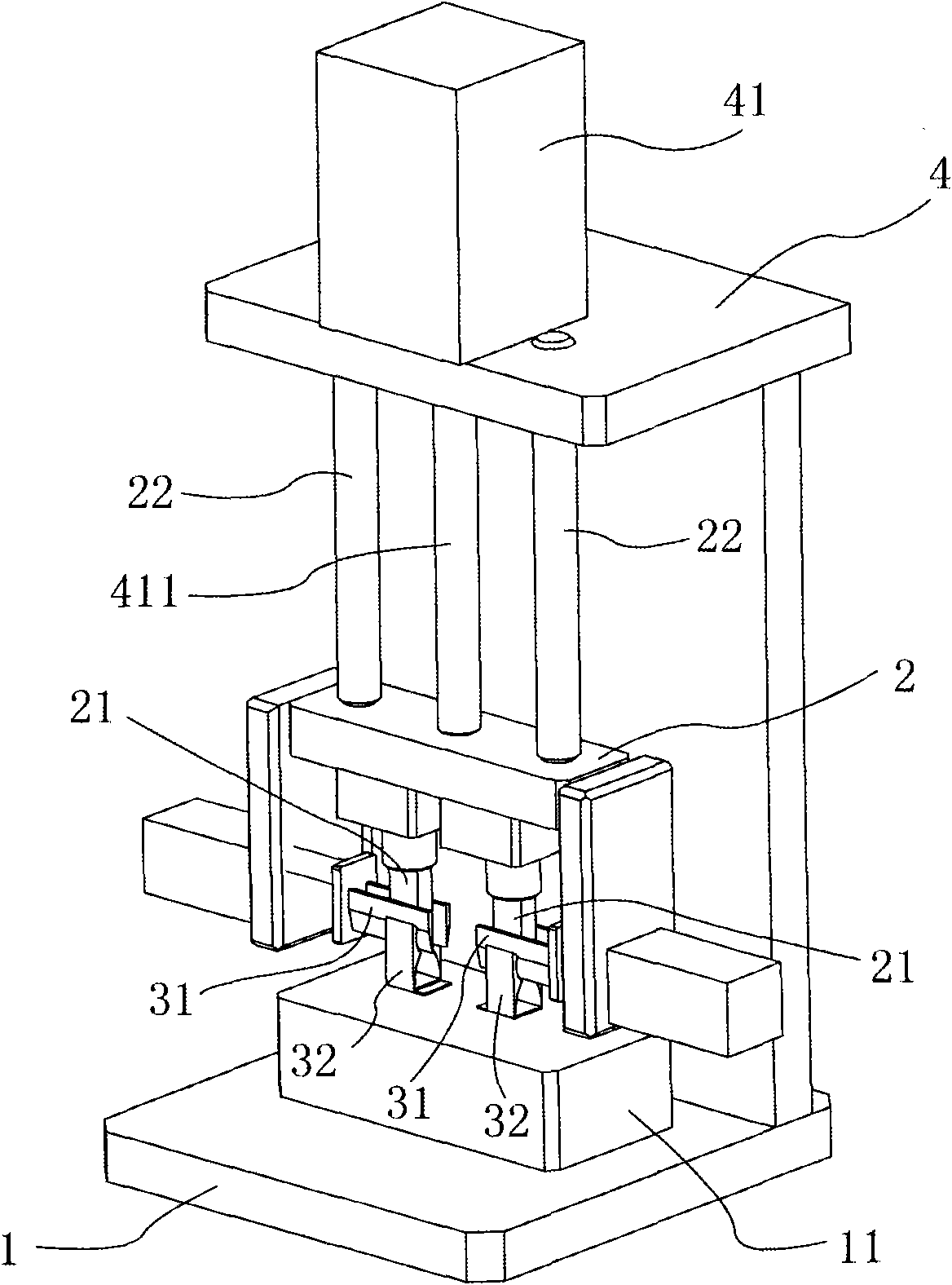
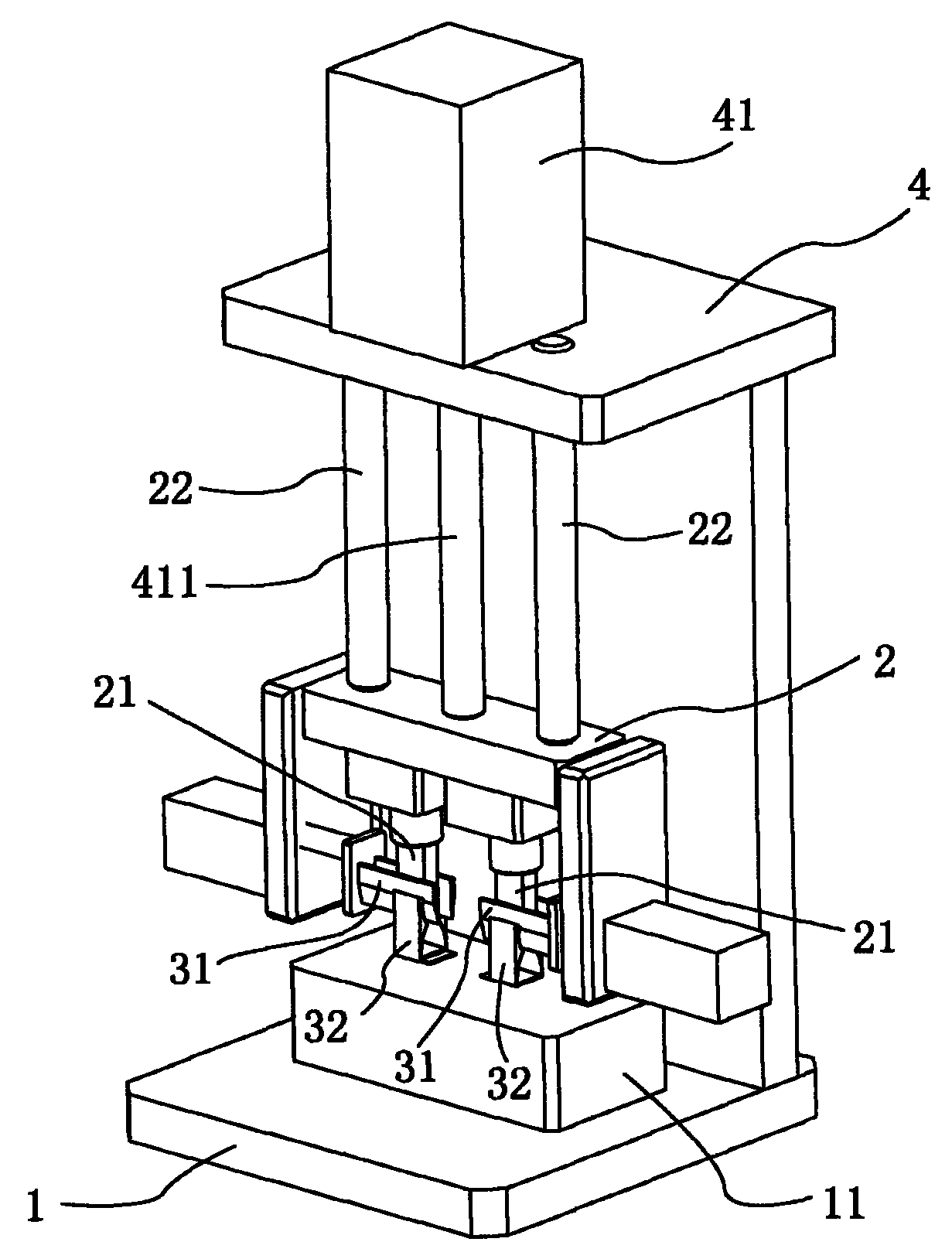
[0014] Such as figure 1 The pressure assembly mechanism shown is mainly used to push a small product into another product. A lower template 11 is arranged on the base 1, and a larger product 32 is placed on the lower template 11 by tools such as clamps. Fixing, the smaller product 31 is placed in the position where the product 32 is combined and assembled and assembled by the pressure of the upper punch 21; the upper punch 21 is installed on the upper die fixing plate 2, and the upper die fixing plate 2 passes through the guide sleeve The guide rods 22 along the left and right sides can slide up and down, and the positions of the upper and lower ends of the guide rods 22 are fixed, wherein the upper end is connected on the cylinder fixed plate 4, and the cylinder 41 is placed on the cylinder fixed plate 41. The head of the piston rod 411 The part is connected with the upper mold fixed plate 2.

[0015] Wherein the rod-shaped head of the upper punch 21 is in contact with the p...


PUM


Abstract

The invention relates to a pressure assembly mechanism, which is used for pressing small products or parts in corresponding cavities of large products or parts. The pressure assembly mechanism comprises an upper punch arranged on an upper die fixed plate and a lower die fixed plate arranged on a base, wherein a guiding sleeve is also arranged on the upper die fixed plate; a guiding rod is arranged in the guiding sleeve; the upper die fixed plate is connected with the head part of a piston rod for driving an air cylinder; the piston rod is parallel to the guiding rod; a clamp for clamping the large products or parts is arranged on the lower die fixed plate; and at least part of the lateral surface of the upper punch along the feeding direction is an inclined plane.

Description

technical field [0001] The invention relates to an assembly mechanism for assembling a small-volume component or product to another large-volume component or product by means of pressure. Background technique [0002] In the process of product assembly, sometimes it is faced with the task of assembling small parts or products with large parts or products, such as embedding small parts into the main body of the product; usually in order to facilitate the mutual assembly of parts Coordination, where the two are in contact, there will be assembly grooves and other structures that are conducive to assembly, but when using external force to squeeze or punch small parts into the main body of the product, sometimes due to the need for strength or insufficient control, The product itself will be deformed, or even deliberately deformed to strengthen the combination of the two; the above-mentioned assembly method will also bring another disadvantage, that is, after the two are assembl...

Claims


Application Information

Patent Timeline
Patent Type & Authority Applications(China)
IPC IPC(8): B23P19/027
Inventor 邓波刘瑞勋
Owner SUZHOU NEW DISTRICT KEXING WILL ELECTRONICS
Why Eureka
Try Eureka