
A method of opening a canal to discharge a dammed lake

A technology of discharge and damming body, applied in the field of emergency flood discharge, can solve the problems of difficult to reach large equipment, difficult to ensure life safety, difficult to control the impact force, etc., to reduce transportation costs and manufacturing costs, in line with social and economic benefits, equipment low cost effect

Active Publication Date: 2016-06-01
广东春天生态科技集团有限公司
View PDF7 Cites 0 Cited by
  • Summary
  • Abstract
  • Description
  • Claims
  • Application Information

AI Technical Summary

Problems solved by technology

The impact force of explosive blasting is difficult to control. Once the control is not good, excessive blasting will occur and the embankment will break, and the situation will be out of control.
The disadvantage of the excavation method of the excavator is that the road leading to the barrier lake is rugged, and large equipment is difficult to reach; the second problem is that the speed of the excavator is very slow and must be operated manually, and it is difficult to guarantee life in case of danger Safety

Method used


Image

  • A method of opening a canal to discharge a dammed lake
  • A method of opening a canal to discharge a dammed lake
  • A method of opening a canal to discharge a dammed lake

Examples


Embodiment 1

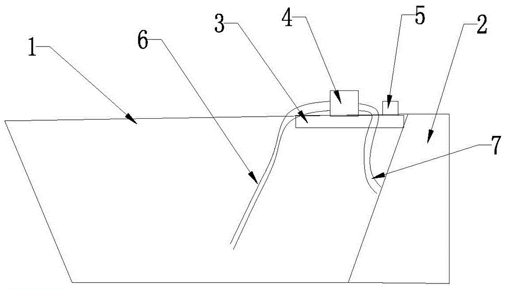
[0030] like figure 1 As shown, a method for draining water from a dammed lake is to place a working platform 3 that can float on the water surface and can carry large-scale equipment on the lake surface 1 of the dammed lake close to the dammed body 2, and the working platform 3 is provided with There are water pumps 4 with high lift and large water volume and power supply equipment 5. One end of the water pump 4 is connected with a suction pipeline 6, which is placed underwater; the other end of the water pump 4 is connected with a drainage pipeline 7, and the outlet of the drainage pipeline 7 faces The lower end of the dam body 2; the water is pumped up from the lake through the water pump 4 and then continuously impacted to the lower end of the dam body 2 through the drainage pipe 7, and the impact force of the water flow is used to make the dam body 2 form a drainage channel. A major feature of the present invention is to place the water pump 4 on the lake surface 1. The pu...

Embodiment 2

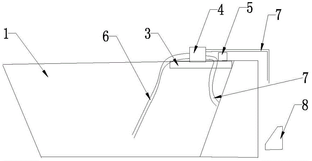
[0046] like image 3 As shown, the difference between this embodiment and Embodiment 1 is that the drainage pipe 7 is spiral. The spiral drainpipe can enhance the impact of water, enhance the ability to open canals, and improve the efficiency of canal openings.

[0047] There are two drainage pipes 7 of the water pump 4, the outlet of one drainage pipe 7 faces the lake water side of the dam body 2, and the water outlet of the other drainage pipe 7 faces the other side of the dam body 2, and An impact type horizontal water turbine 8 is placed below the water outlet, the water turbine 8 is connected with a generator, the generator is connected with the water pump 4, and the power supply device 5 is the generator. Drainage through double pipes, while flushing the dam body 2, is used for hydroelectric power generation, which not only saves resources, but also effectively relieves the water pressure of the dammed lake.

[0048] The water pump 4 is a jet pump, which improves the i...


PUM


Abstract

The invention relates to a rescuing and flood-discharging method and specifically relates to a method for channeling and discharging a barrier lake, wherein the barrier lake adjacent to the barrier lake surface is provided with a working platform which can be exposed out of the water surface and bear large-scale equipment, the working platform is provided with a high-lift pump with high water yield and a power supply unit, one end of the pump is connected with a dewatering pipeline which is arranged below water; the other end of the pump is connected with a drainage pipeline, the outlet end of the drainage pipeline aligns at the lower end of the barrier body; water can be extracted from the lake through the pump and constantly impacted to the lower end of the barrier through the drainage pipeline and the barrier is formed into a drainage galley by water flow impact force, thus the device is low in cost, excellent in security and high in operability.

Description

technical field [0001] The invention relates to a method for emergency flood discharge, in particular to a method for channeling and discharging water from a barrier lake. Background technique [0002] Barrier lakes refer to lakes formed when landslides, earth-rock flows or lava block river valleys or riverbeds and store water to a certain extent. They are usually caused by natural causes such as earthquakes, wind disasters, and volcanic eruptions. There are also barrier lakes created by human factors. For example: explosive firing, engineering excavation, etc. The formation of a barrier lake is usually caused by unstable geological conditions. When the structure of the barrier lake is subjected to erosion, erosion, dissolution, collapse, etc., the barrier lake will appear "overflow", and eventually the barrier lake will The structure is in an extremely poor geological condition, and it evolves into a "broken embankment" and a flash flood occurs instantly, which has devasta...

Claims


Application Information

Patent Timeline
Patent Type & Authority Patents(China)
IPC IPC(8): E02B3/00E02B5/00
CPCE02B1/00E02B1/003
Inventor 林小明
Owner 广东春天生态科技集团有限公司
Learn More