Arc array antenna for MIMO-SAR imaging

A MIMO-SAR, arc array technology, applied in antennas, antenna arrays, and re-radiation, etc., can solve problems such as unfavorable high-resolution imaging observation, achieve imaging observation with a large field of view, improve safety, and improve Observation range effect

Active Publication Date: 2015-01-07
INNER MONGOLIA UNIV OF TECH
View PDF4 Cites 25 Cited by
  • Summary
  • Abstract
  • Description
  • Claims
  • Application Information

AI Technical Summary

Problems solved by technology

Therefore, it is not conducive to high-resolutio

Method used


Image

  • Arc array antenna for MIMO-SAR imaging
  • Arc array antenna for MIMO-SAR imaging
  • Arc array antenna for MIMO-SAR imaging

Examples


Embodiment Construction

[0039] Specific embodiments of the present invention will be described in detail below in conjunction with the accompanying drawings. It should be understood that the specific embodiments described here are only used to illustrate and explain the present invention, and are not intended to limit the present invention.

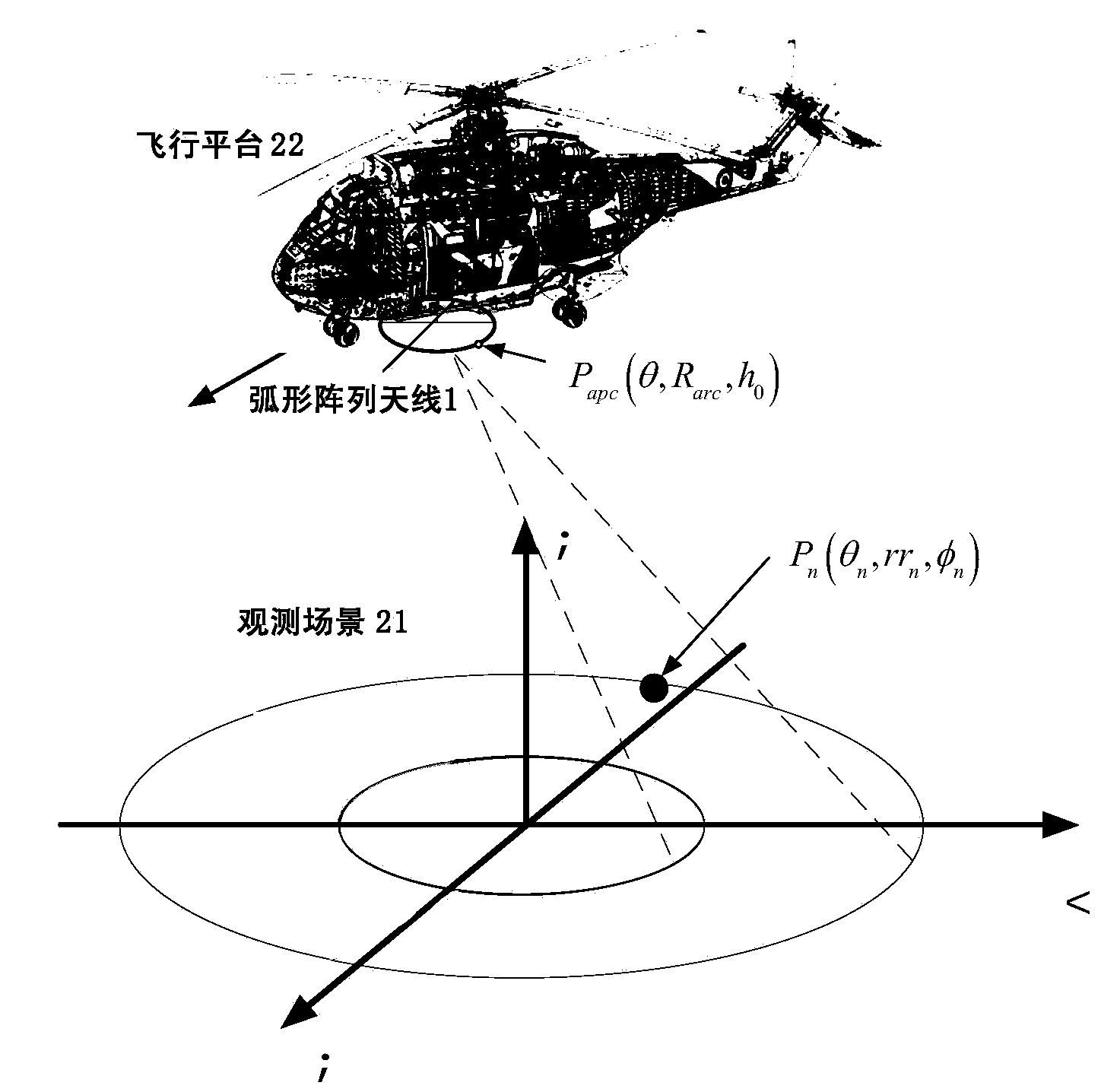
[0040] figure 1 It shows an example platform where the arc array antenna for MIMO-SAR imaging and the microwave signal transceiving system for MIMO-SAR imaging provided by the present invention are applied. Such as figure 1As shown, the arc array antenna 1 and the microwave signal transceiving system can be loaded on the aircraft platform 22 and move with the aircraft platform 22 . The microwave signal transceiving system can radiate microwave signals through the arc array antenna 1 , the microwave signal is reflected by the observation scene 21 to form an echo signal, and then the echo signal is received through the arc array antenna 1 . Afterwards, the echo...


PUM


Abstract

The invention discloses an arc array antenna for MIMO-SAR imaging. The arc array antenna comprises an arc transmitting array antenna body used for radiating a microwave signal, and an arc receiving array antenna body used for receiving an echo signal. All independent transmitting antenna array elements in the arc transmitting array antenna body are arranged in the extending direction of an arc. A radiating port face of each independent transmitting antenna array element faces the outer side of the arc. The arc receiving array antenna body is vertically adjacent to the arc transmitting array antenna body or adjacent to the arc transmitting array antenna body in an inner and outer mode. All independent receiving antenna array elements in the arc receiving array antenna body are arranged in the extending direction of the arc. All the independent receiving antenna array elements and all the independent transmitting antenna array elements are sequentially staggered. A radiating port face of each independent receiving antenna array element faces the outer side of the arc. Accordingly, imaging observation in a large field range can be achieved; in addition, an arc array antenna structure type is adopted, a resolution ratio of the array directions is not reduced along with enlargement of a beam range, relative stability can be kept, and high-resolution imaging observation around an observation platform can be carried out easily.

Description

technical field [0001] The present invention relates to the field of microwave imaging, in particular to an arc array antenna for MIMO-SAR (Multiple-Input Multiple-Output-Synthetic Aperture Radar) imaging. Background technique [0002] Traditional visual, optical or infrared measures are greatly affected by factors such as terrain, weather and day and night, and do not have the ability to work around the clock. The airborne array antenna forward-looking imaging system can not only penetrate smoke, fog, clouds and floating dust, etc., and is not affected by weather and climate, but also can perform real-time high-resolution imaging of the area in front of and below the aircraft, and can provide information for aircraft landing, Reconnaissance, search and rescue and take-off provide real ground information and enhance the aircraft's navigation and transportation rescue capabilities. [0003] The existing airborne array antenna forward-looking imaging system is based on the ai...

Claims


Application Information

Patent Timeline
IPC IPC(8): H01Q21/00G01S7/02G01S13/90
Inventor 黄平平谭维贤洪文
Owner INNER MONGOLIA UNIV OF TECH
Why Eureka
Try Eureka