Draw gear of bogie of railway vehicle

A rail vehicle and traction device technology, which is applied to bogies, devices that move laterally between the bogies and bogies, and underframes, can solve problems such as stiffness characteristics that cannot fully meet design requirements, and fatigue damage to rubber nodes. To achieve variable traction stiffness performance and improve ride comfort

Active Publication Date: 2015-01-14
CRRC QINGDAO SIFANG CO LTD
View PDF7 Cites 15 Cited by
  • Summary
  • Abstract
  • Description
  • Claims
  • Application Information

AI Technical Summary

Problems solved by technology

For this reason, some nodes adopt a structure with gaps to achieve nonlinear stiffness, but the setting of gaps is affected by node size, reliability, an

Method used


Image

  • Draw gear of bogie of railway vehicle
  • Draw gear of bogie of railway vehicle
  • Draw gear of bogie of railway vehicle

Examples


Embodiment 1

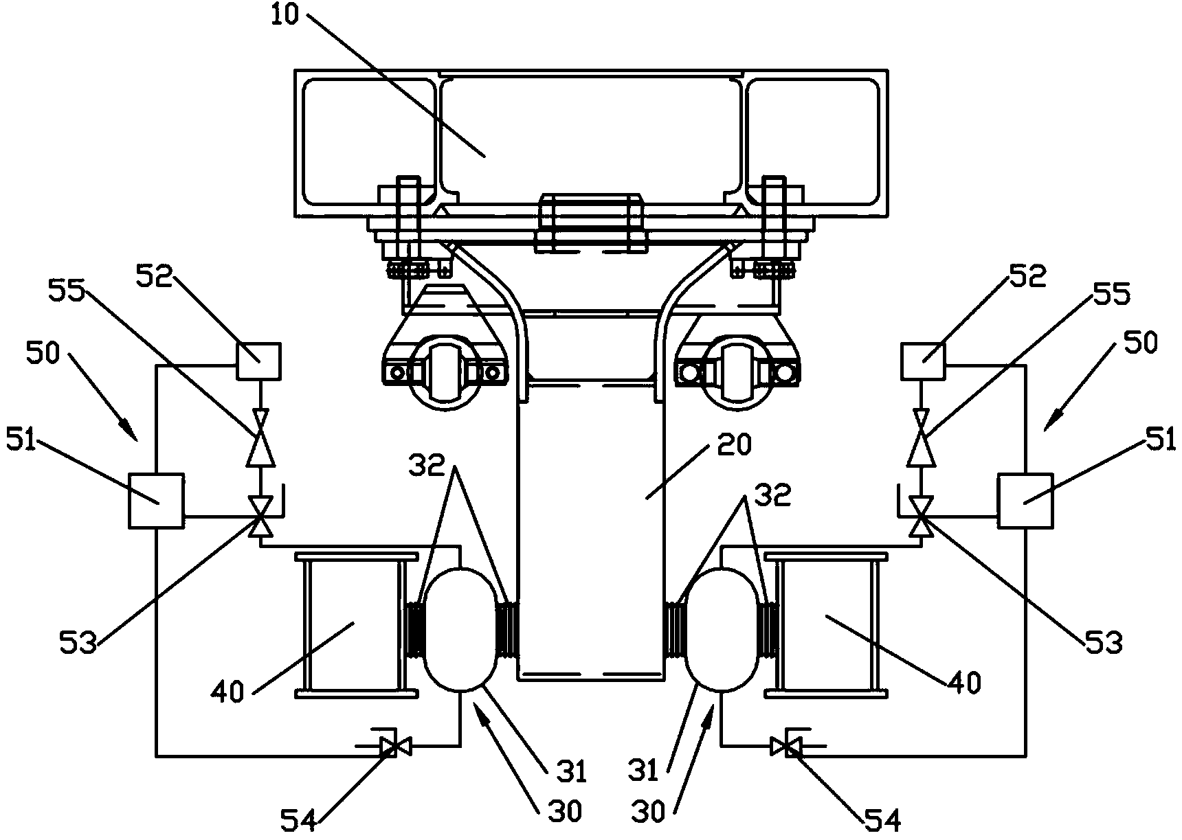
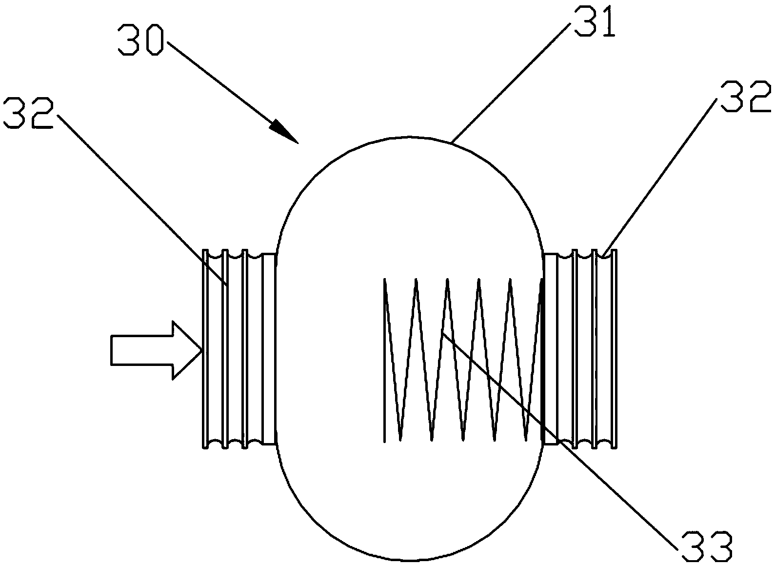
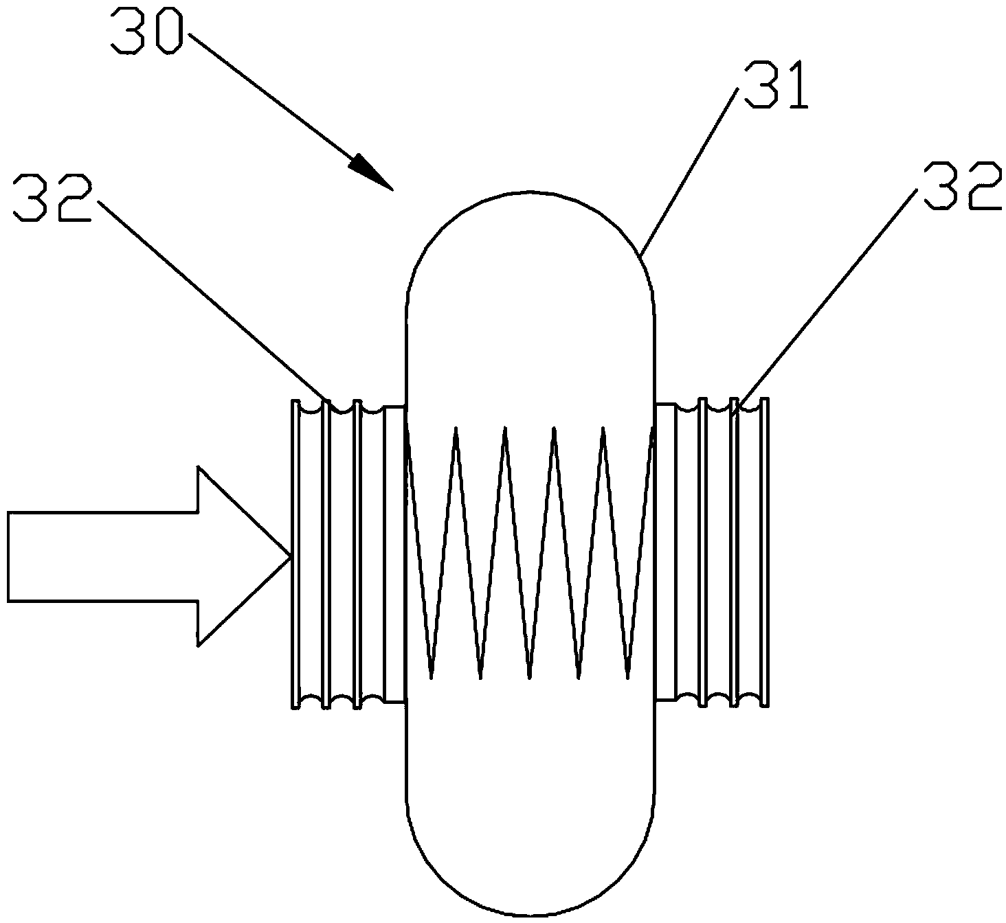
[0025] refer to figure 1 As shown, the railway vehicle bogie traction device of the present invention includes: a central pin 20 and two traction capsules 30; each traction capsule 30 includes a traction rubber pile 32 and a capsule 31, and the body of the capsule 31 is made of rubber. It is provided with a filling port, the capsule 31 is filled with fluid, and the fluid in the capsule 31 is gas or liquid. In this embodiment, the fluid in the capsule 31 is compressed air, and the pressure of the capsule 31 can be set. The traction rubber stack 32 is composed of multiple rubber sheets stacked in sequence to form a columnar structure. The traction rubber stack 32 is connected to the capsule 31 through a flange or glue joint. When the traction rubber pile 32 is connected to the capsule 31 , the axial direction of the traction rubber pile 31 is perpendicular to the capsule 31 , that is, the axis extension of the traction rubber pile 32 passes through the capsule 31 . In this emb...

Embodiment 2

[0033] This embodiment is basically the same as Embodiment 1, except that the rail vehicle bogie traction device in this embodiment also includes a center pin seat, which is rotatably socketed on the center pin; two traction capsules The components are respectively connected with the center pin seat, arranged in a "Z" shape. After installation, the two traction capsules 30 are located on the same level.

[0034] The railway vehicle bogie traction device is located between the frame 40 and the center pin 20 installed on the lower surface of the car body underframe bolster 10 (longitudinal installation), that is, the center pin 20 is fixed on the lower surface of the car body underframe bolster 10 through a bolt assembly. On the surface, the two traction capsules 30 are respectively connected to the front end and the rear end of the frame 40 . The longitudinal stiffness of the capsule 31 can be achieved by setting the inflation and deflation of the pressure control system 50 . ...


PUM


Abstract

The invention relates to the technical field of bogies of railway vehicles, and discloses a draw gear of a bogie of a railway vehicle. The draw gear comprises a center pin and two draw rubber bags. Each draw rubber bag comprises a draw rubber pile and a rubber bag, the rubber bags are filled with liquid, and pressures can be set for the rubber bags; the draw rubber piles are connected with the rubber bags; the center pin is fixed to the lower surface of a body bolster of chassis of a vehicle body of the railway vehicle; one end of each of the two draw rubber bags is connected with the center pin, and the other end of each draw rubber bag is used for being connected with a transverse beam of a framework of the railway vehicle. The draw gear has the advantages that the draw gear has a nonlinear rigid characteristic, accordingly, high-frequency vibration of the framework can be prevented from being transmitted to the vehicle body and the body bolster of the chassis of the vehicle body via the draw gear while longitudinal loads are effectively transmitted, and the riding comfort can be improved.

Description

technical field [0001] The invention relates to the technical field of rail vehicle bogies, in particular to a rail vehicle bogie traction device. Background technique [0002] Rail vehicles generally use traction devices to transfer the longitudinal loads of the car body to the bogie. At present, the existing traction devices mainly include single-rod type and Z-shaped double-rod type. Both types of traction devices are respectively connected to the center pin of the car body and the frame through the traction rods with rubber nodes at both ends, as the car body and bogie. The connecting mechanism between them is likely to become the transmission path of harmful vibration. The study found that the stiffness of the traction rod is closely related to the vibration comfort of the vehicle body. For this reason, some nodes adopt the structure of setting gaps to achieve nonlinear stiffness, but the setting of gaps is affected by node size, reliability and gap stability, etc., a...

Claims


Application Information

Patent Timeline
IPC IPC(8): B61F5/50
CPCB61F5/50B61F5/16B61F5/245B61F5/24B61F1/14
Inventor 虞大联李海涛曲文强刘韶庆林俊邓小军龚明梁建英
Owner CRRC QINGDAO SIFANG CO LTD
Why Eureka
Try Eureka