A hydraulic safety clamping device for experimental electronic equipment

A technology of electronic equipment and clamping device, which is applied in the field of hydraulic safety clamping device for experimental electronic equipment, which can solve the problems of small deformation of the clamping device, not suitable for short-distance bending, excessive force on the screen, etc., and achieve an adjustable range Large, easy to manufacture, and strong operability

Inactive Publication Date: 2016-01-20
XIAN UNIV OF SCI & TECH
View PDF8 Cites 0 Cited by
  • Summary
  • Abstract
  • Description
  • Claims
  • Application Information

AI Technical Summary

Problems solved by technology

Lifting by people is not only easy to fatigue, but also unstable
At present, the clamping device used in the laboratory is mainly a rod that can be bent arbitrarily and maintains deformation under a certain strength. This kind of clamping device mainly has the following disadvantages in the actual use process: (1) In order to ensure the deformation of the deformable rod, the bending strength of the rod is relatively large, and it is not suitable for short-distance bending, and there are some unbalanced forces in some bending forms during use , which requires repeated trials, which is very inconvenient; (2) The power source of the electronic device clamping device is mainly the spring installed on the clip. (3) The deformation of the clamping device is too small, that is, when the screen of the electronic equipment is narrow and the clamping force is small, the clamping is unstable, easy to fall off, and damages the electronic equipment

Method used


Image

  • A hydraulic safety clamping device for experimental electronic equipment
  • A hydraulic safety clamping device for experimental electronic equipment
  • A hydraulic safety clamping device for experimental electronic equipment

Examples


Embodiment Construction

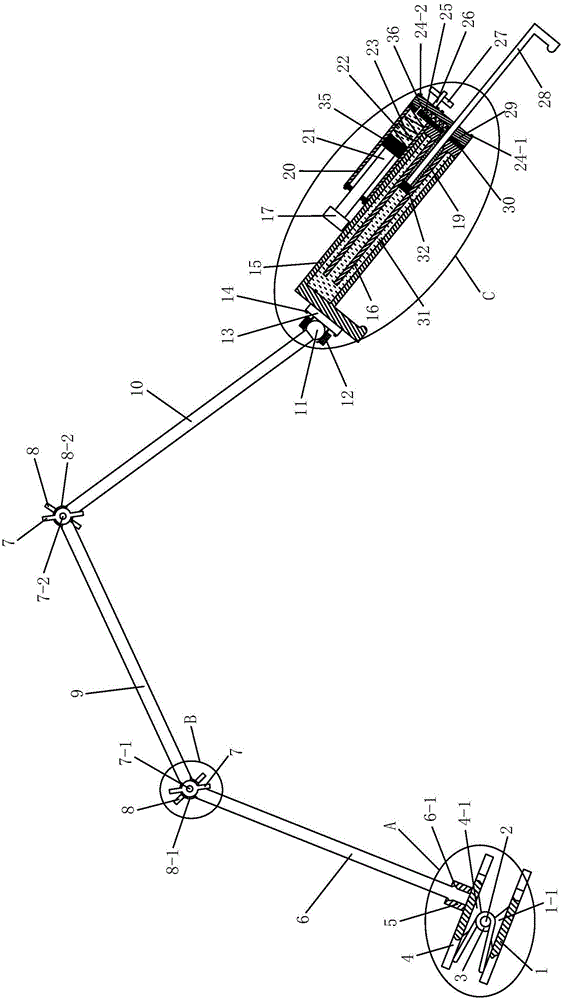
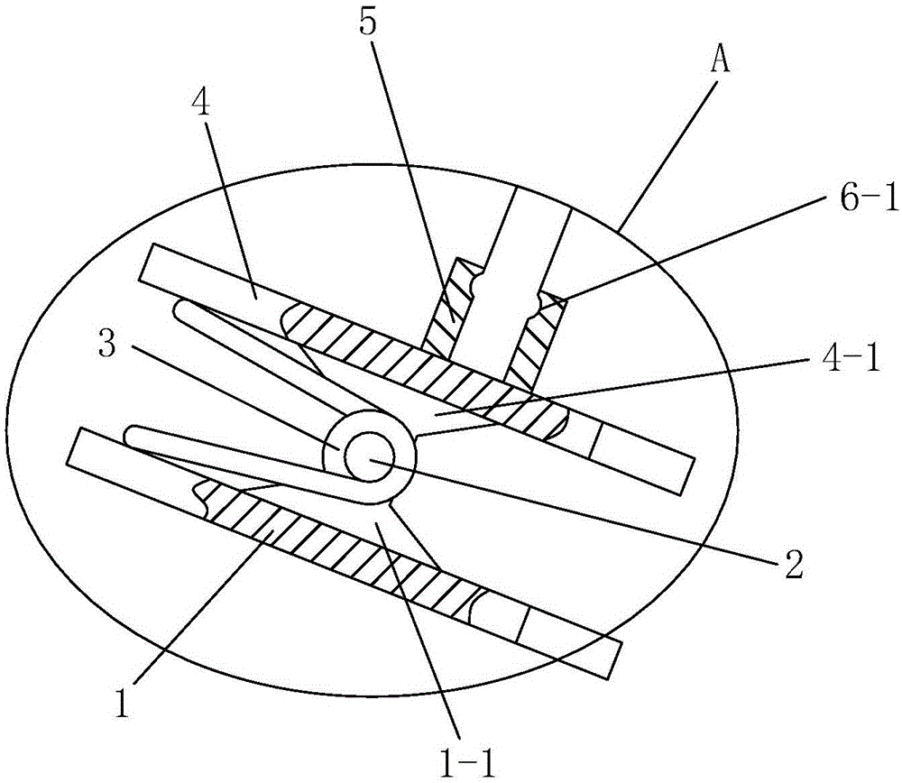
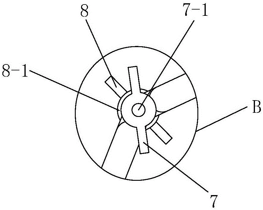
[0043] Such as Figure 1 to Figure 6As shown, the present invention includes a fixed clip, a connecting rod group and a clamping mechanism connected in sequence, the top of the fixed clip is fixed with a shaft sleeve 5, and one end of the connecting rod group extends into the shaft sleeve 5 and is connected with the shaft sleeve 5 Rotationally connected, the other end of the connecting rod group is fixed with a universal ball 11, and the clamping mechanism includes a clamping cylinder 15, an inner cylinder 16, a clamping rod 28, a booster cylinder 20 and a booster rod 21 , the top of the clamping cylinder 15 is fixed with a universal ball base 13, the universal ball 11 is arranged in the universal ball base 13, and the clamping cylinder 15 is sleeved on the inner cylinder 16, The lower end of the inner cylinder 16 is located outside the clamping cylinder 15, and the bottom of the inner cylinder 16 is provided with a leak-proof baffle 30, and the bottom of the leak-proof baffle...


PUM


Abstract

The invention discloses a hydraulic safety clamping device for experiment electronic equipment. The hydraulic safety clamping device comprises a fixing clamp, a connecting rod set and a clamping mechanism which are sequentially connected. One end of the connecting rod set is connected with the fixing clamp, and the other end of the connecting rod set is fixedly connected with a universal ball. The clamping mechanism comprises a clamping cylinder body, an inner cylinder body, a clamping rod, a pressurizing cylinder body and a pressurizing rod. The top of the clamping cylinder body is fixedly connected with a universal ball base, the universal ball is arranged in the universal ball base, and the clamping cylinder body is arranged on the inner cylinder body in a sleeving mode. A leakage-proof baffle and a pedestal are arranged at the bottom of the inner cylinder body. One end of the clamping rod stretches into the inner cylinder body, one end of the pressurizing rod stretches into the pressurizing cylinder body, and a spring is arranged in the pressurizing cylinder body. A first channel, a second channel and a third channel are formed between the leakage-proof baffle and the pedestal. A first one-way valve is mounted on the first channel, a second one-way valve is mounted on the second channel, the mounting direction of the first one-way valve is opposite to the mounting direction of the second one-way valve, and the third channel is provided with a pressure release valve. By means of the hydraulic safety clamping device for the experiment electronic equipment, the electronic equipment can be stably fixed, and the damage and disengaging phenomena can be avoided.

Description

technical field [0001] The invention relates to a clamping device for experiments, in particular to a hydraulic safety clamping device for electronic equipment used in experiments. Background technique [0002] Many equipment used in the laboratory, such as photographic equipment, camera equipment, projection equipment and other electronic equipment, need to be lifted by hand for a long time, or need to be fixed on the edge of the laboratory table or cabinet by means of a clamping device, which has satisfied Usage requirements. Lifting by people is not only easy to fatigue, but also unstable. At present, the clamping device used in the laboratory is mainly a rod that can be bent arbitrarily and maintains deformation under a certain strength. This kind of clamping device mainly has the following disadvantages in the actual use process: (1) In order to ensure the deformation of the deformable rod, the bending strength of the rod is relatively large, and it is not suitable fo...

Claims


Application Information

Patent Timeline
Patent Type & Authority Patents(China)
IPC IPC(8): B25B11/00
CPCB25B11/00
Inventor 田水承陈盈李广利邹元王莉孙庆兰施文鑫
Owner XIAN UNIV OF SCI & TECH
Why Eureka
Try Eureka