Automatic wire feeder

A wire feeder and automatic technology, applied in the field of wire harness processing, can solve problems such as slippage, unstable size, and unstable cutting length

Active Publication Date: 2015-01-28
江苏融威实业有限公司
View PDF4 Cites 11 Cited by
  • Summary
  • Abstract
  • Description
  • Claims
  • Application Information

AI Technical Summary

Problems solved by technology

[0002] In the field of wire harness processing, such as computer wire stripping machines, pipe cutting machines and other equipment will involve the delivery of wire harnesses. The existing wire feeder generally passes the wire harness through a movable wheel, and the up and down movement of the movable wheel can control the pay-off reel. Turning and stopping, when the wire harness is consumed, the movable wheel moves upwards by the pulling force of the wire harness, and the wire payoff is controlled to release t

Method used


Image

  • Automatic wire feeder
  • Automatic wire feeder
  • Automatic wire feeder

Examples


Embodiment Construction

[0019] The specific implementation manners of the present invention will be further described in detail below in conjunction with the accompanying drawings and embodiments. The following examples are used to illustrate the present invention, but are not intended to limit the scope of the present invention.

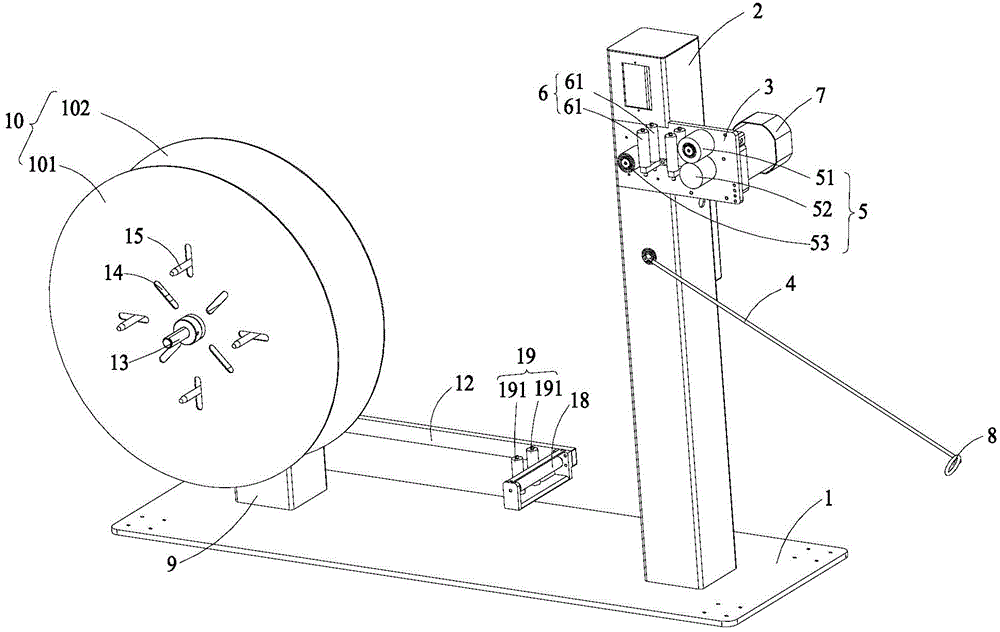
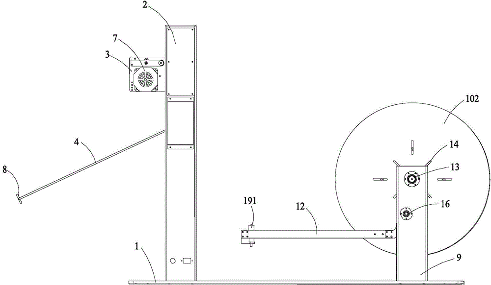
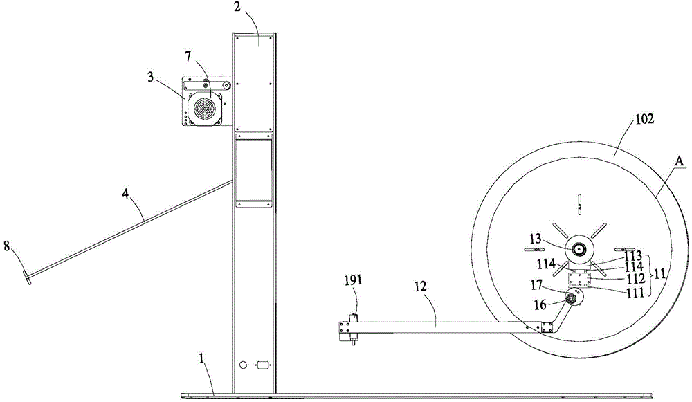
[0020] see Figures 1 to 4 As shown, an automatic wire feeder shown in an embodiment of the present invention includes a machine base 1, a conveying system arranged on the machine base 1, and a wire pay-off system arranged on one side of the conveying system.

[0021] The conveying system includes a first column 2 arranged on the machine base 1, a square fixed plate 3 fixed on the first column 2, a delivery detection swing arm 4 arranged on the first column 2 and below the fixed plate 3, and a The photoelectric detection sensor (not shown) used to detect the swing position of the delivery detection swing arm 4 on the first column 2, the photoelectric detection sensor mode...


PUM


Abstract

The invention relates to an automatic wire feeder comprising a conveying system and a pay-off system arranged on one side of the conveying system. The conveying system comprises a first column, a horizontal wire feeding roller set arranged on the first column, a conveying motor used for driving the horizontal wire feeding roller set, a conveying detection swing arm arranged on the first column and a photoelectric detection sensor, the photoelectric detection sensor is used for detecting the swinging position of the conveying detection swing arm and controlling the conveying motor to start according to the position of the conveying detection swing arm, a wire passing hole is arranged in the free end of the conveying detection swing arm and located under the horizontal wire feeding roller set, the pay-off system comprises a second column, a pay-off reel fixed on the second column through a pay-off spindle, a brake and a brake driving swing arm, the brake is fixed on the second column, one end of the brake driving swing arm is fixed to the second column through a rotating shaft, the other end of the brake driving swing arm is a free end which is provided with a horizontal wire passing wheel, and the brake driving swing arm swings up and down to enable the brake to tightly hold or release the pay-off spindle.

Description

technical field [0001] The invention belongs to the field of wire harness processing, in particular to an automatic wire feeder. Background technique [0002] In the field of wire harness processing, such as computer wire stripping machines, pipe cutting machines and other equipment will involve the delivery of wire harnesses. The existing wire feeder generally passes the wire harness through a movable wheel, and the up and down movement of the movable wheel can control the pay-off reel. Turning and stopping, when the wire harness is consumed, the movable wheel moves upwards by the pulling force of the wire harness, and the wire payoff is controlled to release the wire harness, and then the movable wheel descends, and the wire payoff is controlled to stop unwinding, and the wire harness continues to move upwards after the wire harness is consumed, so as to reciprocate the length of the wire feeding , In this process, the wire harness is subjected to a large and unstable tens...

Claims


Application Information

Patent Timeline
IPC IPC(8): B65H51/08B65H51/30
Inventor 张金斌
Owner 江苏融威实业有限公司
Why Eureka
Try Eureka