A Wiring Mechanism for Easy Alignment

A convenient, box-based technology, applied in the direction of electrical components, etc., can solve the problems of strengthening the work strength of operators, inconvenient docking of bolts and junction boxes, and increasing the difficulty of junction boxes, so as to reduce labor intensity, shorten operation time, and reduce procedures Effect

Active Publication Date: 2016-10-12
CHENGDU ZHIRONG ZHICHUANG INTPROP MANAGEMENT CO LTD
View PDF6 Cites 0 Cited by
  • Summary
  • Abstract
  • Description
  • Claims
  • Application Information

AI Technical Summary

Problems solved by technology

The existing iron junction box is highly used in the industry because of its low cost and simple processing and operation. However, after the junction box is installed and the connected wire ends are sealed, due to the type and diameter of the bolt and screw hole Small size, the connection between the bolt and the junction box is very inconvenient, and the operator needs to make multiple attempts, especially when sealing the junction box on the ceiling, the operator needs to work at heights for a long time and hold his hands high, which not only increases the difficulty of sealing the junction box , It also greatly strengthens the work intensity of the operator. At the same time, due to the large number of junction boxes in the wiring process, the high-strength junction box seal also reduces the safety and reliability of high-altitude operations.

Method used


Image

  • A Wiring Mechanism for Easy Alignment
  • A Wiring Mechanism for Easy Alignment
  • A Wiring Mechanism for Easy Alignment

Examples


Embodiment 1

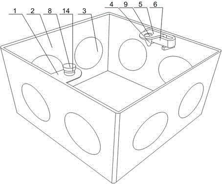
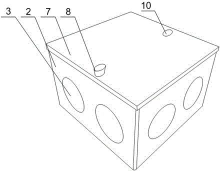
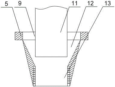
[0023] Such as Figure 1 to Figure 4 As shown, this embodiment includes a box body 2 with one end open and a cover plate 7 matched with the box body 2, and a fixed part 1 and a movable cavity are respectively installed on a group of mutually parallel sides of the open part of the box body 2. 6. There is a through hole on the fixed part 1, and the end of the rotating body 8 is threadedly matched with the through hole. In the cavity 6, the movable part 5 is provided with a correction hole 9 whose aperture is larger than the aperture of the through hole, and the lower end of the correction hole 9 is connected with an extension part 4, and the inside of the extension part 4 is provided with a tapered cavity and a screw thread connected to each other. A through hole 13, and the tapered cavity communicates with the correction hole 9; also includes a screw hole 10 arranged on the cover plate 7 and corresponding to the correction hole 9. During the work of the present invention, the ...

Embodiment 2

[0026] Such as figure 1 As shown, this embodiment is based on Embodiment 1, and the middle part of the rotating body 8 is provided with an annular groove 14 , and the cover plate 7 is rotatably arranged in the annular groove 14 . One end of the cover plate 7 is set on the rotating body 8 by turning, and is set on the fixed part 1 together with the rotating body 8, so that the cover plate 7 can move relative to the box body 2, reducing the need for workers to tighten the bolts 11 The number of times, and facilitate the opening of the cover plate 7 during line maintenance or detection.

Embodiment 3

[0028] Such as figure 1 As shown, this embodiment is based on the embodiment 1, and a plurality of joint holes 3 are opened on the four side walls of the box body 2 , and sealing covers are welded on the joint holes 3 . The installation method of the sealing cover installed on the joint hole 3 is spot welding, that is, the part of the sealing cover is connected to the box body 2 by spot welding to realize the sealing of the joint hole 3. When the box body 2 needs to be connected in any direction around the When the line pipe is used, the sealing cover is directly taken out, and the box body 2 is connected with the line pipe through a straight pipe or an elbow joint, so as to improve the practicability of the present invention.


PUM


Abstract

The invention discloses a wiring mechanism convenient to align. The wiring mechanism comprises a box body with an open end and a cover plate matched with the box body. A fixed part and a movable cavity are arranged on a group of parallel sides of the open part of the box body respectively. A through hole is formed in the fixed part. The end of a rotating body is matched with the through hole in a thread mode. The cover plate is arranged on a rotating body in a rotating mode. A movable part is arranged in the movable cavity in a sliding mode. A correcting hole with the hole diameter larger than that of the through hole is formed in the movable part. The lower end of the correcting hole is connected with an extending part. A cone-shaped cavity and a thread through hole which are communicated with each other are formed in the extending part. The cover plate is fixed on the box body through the rotating body, so that when a worker carries out box body sealing, the worker only needs to use a single bolt for fixing, the processes for wiring box sealing are reduced, working time is shortened, during bolt fixing, operation is easy, sealing of the cover plate and the box body is accelerated, and the labor intensity of workers is greatly lowered.

Description

technical field [0001] The invention relates to the field of petroleum machinery, in particular to a wiring mechanism for convenient alignment. Background technique [0002] The power cable wiring in the oil warehouse should meet the following requirements: 1. The laying method of the cable wiring should be comprehensively determined according to the engineering conditions, environmental characteristics, cable type and quantity and other factors, and in accordance with the principles of reliable operation, easy maintenance, technical and economical rationality, etc. ; 2. The selection of the cable path should meet the following requirements: 1) The cable should be protected from mechanical external force, overheating, corrosion and other hazards; 2) It should be easy to lay and maintain; 3) It should avoid the construction land or construction land in the site planning ; 4) The cable path should be the shortest when the safety conditions are met; 3. When the cable is laid in...

Claims


Application Information

Patent Timeline
Patent Type & Authority Patents(China)
IPC IPC(8): H02G3/08H02G3/14
Inventor 贺昶明
Owner CHENGDU ZHIRONG ZHICHUANG INTPROP MANAGEMENT CO LTD
Why Eureka
Try Eureka