Electrical cabinet with fixed structure at the end of the wire slot

A fixed structure and wire slot technology, applied in the field of electrical cabinets, can solve problems such as troublesome operation of wire slot fixing, and achieve the effect of convenient operation and improved stability

Active Publication Date: 2017-05-03
广州盛美电气设备有限公司
View PDF3 Cites 0 Cited by
  • Summary
  • Abstract
  • Description
  • Claims
  • Application Information

AI Technical Summary

Problems solved by technology

[0004] The technical problem to be solved by the present invention is to provide an electrical cabinet with a fixed structure at the end of the wire slot to overcome the troublesome problem of fixing the wire slot in the existing electrical cabinet

Method used


Image

  • Electrical cabinet with fixed structure at the end of the wire slot
  • Electrical cabinet with fixed structure at the end of the wire slot
  • Electrical cabinet with fixed structure at the end of the wire slot

Examples


Embodiment

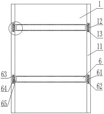
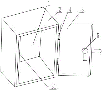
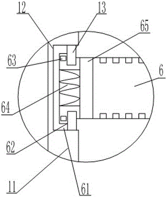
[0021] Such as Figure 1 to Figure 3 As shown, the electrical cabinet with a fixed structure at the end of the wire insertion slot includes a bottom plate 1, a side plate 2, and a cover plate 3 connected to the side plate 2 through a hinge 4. The cover plate 3 is provided with a switch 5 and is provided with a switch 5 The upper end of the side plate 2 opposite to the side plate is provided with a flange 21, and the two sides of the bottom plate 1 are provided with bumps 11, and each bump 11 is provided with at least two grooves 12, and on the side wall opposite to the groove 12 A baffle 13 is provided, a boss is provided on the upper end of the baffle 13, a wire insertion groove 6 is arranged in the groove 12, and an elastic connecting piece 65 is arranged on the end of the wire insertion groove 6, the connecting piece 65 is rubber, and the connecting piece The end of 65 is connected with the fixed block that is arranged as the clamping structure that spring 64 two ends are a...


PUM


Abstract

The invention relates to an electrical cabinet with a fixing structure at the ends of a wire inserting slot. The electrical cabinet with the fixing structure at the ends of the wire inserting slot comprises a baseboard, side plates and a cover plate. A switch is arranged on the cover plate. A flange is arranged at the upper end of the side plate opposite to the cover plate with the switch. Protruding blocks are arranged on the two sides of the bottom plate. Each protruding block is provided with at least two grooves. The opposite side walls of each groove are each provided with a baffle. The wire inserting slot is arranged in the grooves. Elastic connecting sheets are arranged at the ends of the wire inserting slot. The ends of each connecting sheet are connected with a fixing block of a clamping structure, wherein a spring is arranged in the middle of each clamping structure, sliding blocks are arranged at the two ends of each clamping structure, and through grooves are formed in the two sides of each sliding block. According to the electrical cabinet with the fixing structure at the ends of the wire inserting slot, the elastic connecting sheets are arranged at the ends of the wire inserting slot, and the ends of each connecting sheet are connected with a fixing block with each clamping structure, wherein the spring is arranged in the middle of each clamping structure, and the sliding blocks are arranged at the two ends of each clamping structure; through grooves are formed in the two sides of each sliding block, the baffles are controlled to be fixed into and taken out of the through grooves through compression of the springs, and the problem that fixing of the wire inserting slot of an existing electrical cabinet is complex in operation is solved.

Description

technical field [0001] The invention relates to the field of electrical cabinets, in particular to an electrical cabinet with a fixed structure at the end of a wire slot. Background technique [0002] Today, electricity is an energy source that occupies a very large share in a country. Whether it is in the operation of elevators or in the manufacture of many tools, it needs to be used in electrical appliances and electrical cabinets. With the rapid development of the economy, China's demand for electrical appliances is becoming more and more obvious, and the application of electrical cabinets is becoming more and more extensive. [0003] The electrical cabinet is a cabinet used to install electrical equipment, and has the function of protecting the electrical equipment installed inside it. The electrical cabinet mainly includes a rectangular frame-shaped base for installing electrical equipment, and a cabinet door matched with the base. When the existing electrical cabinet ...

Claims


Application Information

Patent Timeline
Patent Type & Authority Patents(China)
IPC IPC(8): H05K7/02
Inventor 李健忠
Owner 广州盛美电气设备有限公司
Why Eureka
Try Eureka