Heat exchanger and air conditioner provided with said heat exchanger

A technology of heat exchangers and heat exchanger parts, applied in the field of heat exchangers and air conditioners, can solve the problems of heat exchanger performance and high cost, achieve low price, performance realization, and improve heat exchange efficiency

Inactive Publication Date: 2015-01-28
MITSUBISHI ELECTRIC CORP
View PDF13 Cites 3 Cited by
  • Summary
  • Abstract
  • Description
  • Claims
  • Application Information

AI Technical Summary

Problems solved by technology

Therefore, an air conditioner equipped with a conventional heat exchanger has a problem of high cost for the performance of the heat exchanger.

Method used


Image

  • Heat exchanger and air conditioner provided with said heat exchanger
  • Heat exchanger and air conditioner provided with said heat exchanger
  • Heat exchanger and air conditioner provided with said heat exchanger

Examples


Embodiment approach 1

[0040] In the heat exchanger according to Embodiment 1, fin pitches in some ranges are formed to be larger than fin pitches in other ranges by an assembling method different from conventional ones in which fin pitches can be easily changed. In addition, the air conditioner according to the first embodiment includes the heat exchanger according to the first embodiment in which the fin density is optimally arranged in consideration of the internal structure of the case, and can achieve energy saving and low cost while maintaining performance equivalent to conventional ones. Cost, low price.

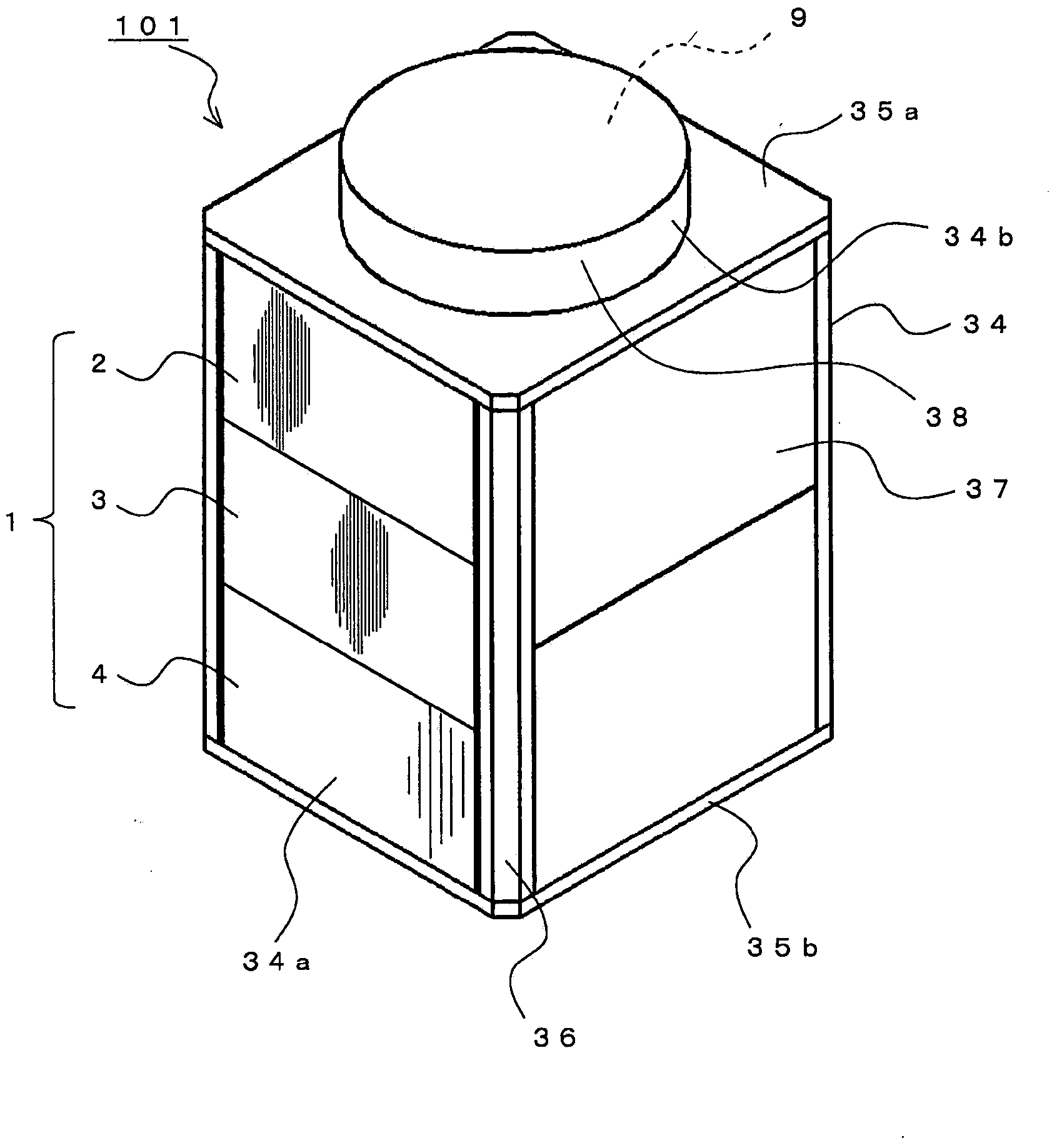
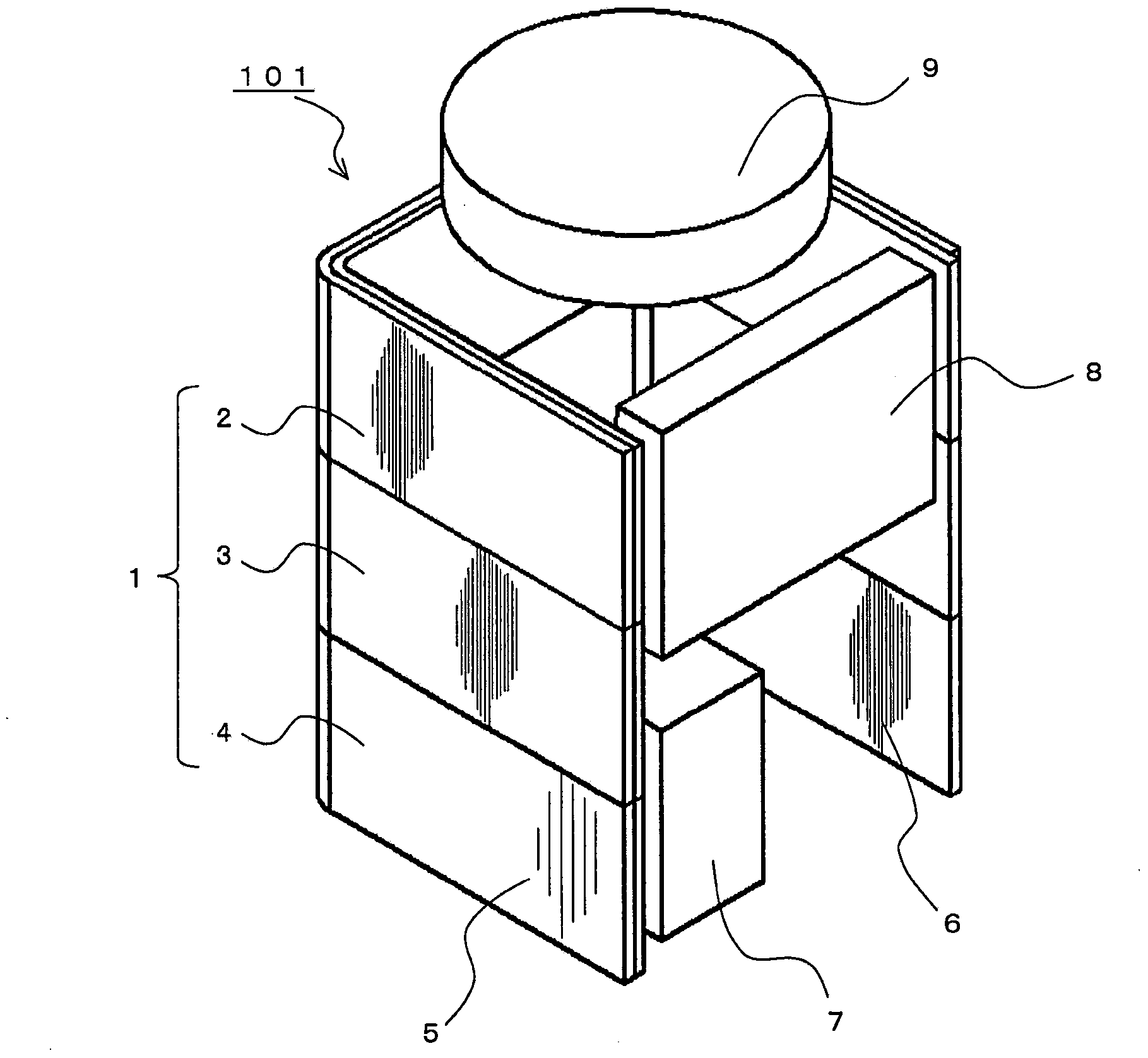
[0041] Hereinafter, the heat exchanger according to Embodiment 1, the method of manufacturing the heat exchanger according to Embodiment 1, and the air conditioner according to Embodiment 1 will be described in detail. In addition, below, the air conditioner of this Embodiment 1 is demonstrated taking the outdoor unit which mounted the heat exchanger of this Embodiment 1 as an example.

[...

Embodiment approach 2

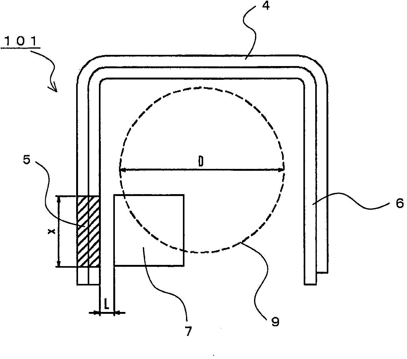
[0081] In Embodiment 1, as an example of changing the fin pitch in a partial range of the heat exchanger 1 , an example of changing the fin pitch in the compressor housing adjacent range 5 close to the compressor housing 7 was described. However, the range of changing the fin pitch is not limited to the compressor housing adjacent range 5 . It is also possible to vary the fin spacing of the heat exchanger 1 in the following ranges together with the compressor housing adjacent range 5 or separately from the compressor housing adjacent range 5 . In addition, in this Embodiment 2, about the structure which is not specifically described, it is the same as Embodiment 1, and the same code|symbol is used for the same function and structure.

[0082] Figure 7 It is a top sectional view showing the heat exchanger and the control panel 8 in the outdoor unit according to Embodiment 2 of the present invention from the propeller fan side.

[0083] As in the first embodiment, the outdoor...

Embodiment approach 3

[0092] The example of changing the fin pitch in a part of the range of the heat exchanger 1 is not limited to that shown in Embodiment 1 and Embodiment 2, and may be combined with or different from the structure of at least one of Embodiment 1 and Embodiment 2. From the structure of Embodiment 1 and Embodiment 2, the fin pitch of the heat exchanger 1 is changed in the following range. In addition, in Embodiment 3, the configurations not particularly described are the same as in Embodiment 1 or Embodiment 2, and the same functions and configurations are described using the same reference numerals.

[0093] Figure 9 It is a top cross-sectional view showing the heat exchanger in the outdoor unit according to Embodiment 3 of the present invention from the side of the propeller fan. Should Figure 9 The shown blank arrows indicate the flow of air inside the outdoor unit 101 .

[0094] The heat exchanger 1 according to Embodiment 3 is divided into two rows of heat exchanger sect...


PUM


Abstract

This heat exchanger (1) is provided with: a plurality of fins (12) stacked at a predetermined fin pitch; and a plurality of flat-cross-sectioned heat transmission tubes (10) that penetrate the fins (12) along the direction of stacking. In the fins (12), a plurality of notches (13) are formed at the ends in the lengthwise direction thereof and having a shape corresponding to the cross-sectional shape of the heat transmission tubes (10); a collar (14) is formed at the edge of the notches (13); the heat transmission tubes (10) are inserted into the notches (13); the fin pitch between a subset of the plurality of fins (12) is larger than the fin pitch between the remaining fins (12); and at least the larger fin pitch is greater than the height of the collars (14).

Description

technical field [0001] The present invention relates to a heat exchanger and an air conditioner including the heat exchanger. Background technique [0002] Conventionally, heat exchangers of air conditioners have mostly adopted a flat-finned tube structure in which a plurality of plate-shaped aluminum fins with circular holes formed therein are stacked at predetermined fin pitches. Insert a plurality of copper or aluminum heat transfer tubes with a circular cross-section in the stacking direction of the fins (hereinafter, also referred to as fin groups), and then use a hydraulic or mechanical tube expander to expand the inner diameter of the heat transfer tubes , thereby ensuring the adhesiveness between the fins and the heat transfer tubes required for the heat transfer performance of the heat exchanger (for example, refer to Patent Document 1). [0003] In addition, in order to increase the area where the fins and the heat transfer tubes are in close contact, the edges of...

Claims


Application Information

Patent Timeline
Patent Type & Authority Applications(China)
IPC IPC(8): F28F1/32F24F5/00F28F1/18
CPCF24F1/18F28F1/32F28F1/18F28F2215/12F28D1/024F28D1/0476F28F2215/04F28F2215/14F28F1/12
Inventor 池田亮一村田明生三宅展明冈泽宏树铃木涉松田拓也
Owner MITSUBISHI ELECTRIC CORP
Why Eureka
Try Eureka