Eureka AIR delivers breakthrough ideas for toughest innovation challenges, trusted by R&D personnel around the world.

Electrode used for dry etching device and preparation method thereof, and dry etching device

A dry etching, electrode technology, applied in the direction of circuits, discharge tubes, electrical components, etc., can solve the problems of etching ability difference, poor, poor etching effect, etc., to achieve the effect of avoiding maintenance operations

Inactive Publication Date: 2015-02-04
HEFEI BOE OPTOELECTRONICS TECH +1
View PDF4 Cites 2 Cited by
  • Summary
  • Abstract
  • Description
  • Claims
  • Application Information

AI Technical Summary

Problems solved by technology

[0006] However, if figure 2 As shown, when the dry etching equipment bombards the metal layer on the substrate 1, metal atoms will be sputtered, and the metal atoms will react with the reaction gas to form a metal compound, most of which will be drawn out of the etching chamber, but in the electric field of the chamber and Under the complex action of gas flow, the metal compound will inevitably partially remain on the surface of the electrode 2, especially when the metal etching process will produce a molybdenum (Mo) compound. After long-term use of the electrode, due to the molybdenum (Mo) compound and other by-products ( figure 2 middle black filled area) remains on the protrusion 21, the surface of the protrusion 21 will be in surface contact with the glass substrate 1 due to the adhesion of reactants and by-products, and when the cooling gas is introduced, the protrusion 21 will quickly contact the corresponding glass substrate 1 for heat exchange, so that the temperature of this part of the glass substrate 1 is rapidly reduced; and the part of the glass substrate 1 around the protrusion 21 is in contact with the cooling gas for heat exchange, and its heat exchange rate is relatively slow. 1 The temperature drops slowly; therefore, temperature differences will occur on the entire surface of the glass substrate 1, resulting in differences in the etching capabilities between the position of the protrusion 21 and the adjacent area, resulting in poor etching effects, which will seriously affect the prepared thin film transistor device performance and cause poor display of the final product
The longer the electrode 2 is used, the worse the adverse results will be
[0007] At present, periodic electrode 2 cleaning and electrode 2 surface ceramic peeling repair are generally used to improve the bad etching effect, and the labor cost and maintenance cost are high.

Method used


Image

  • Electrode used for dry etching device and preparation method thereof, and dry etching device
  • Electrode used for dry etching device and preparation method thereof, and dry etching device
  • Electrode used for dry etching device and preparation method thereof, and dry etching device

Examples


Embodiment 1

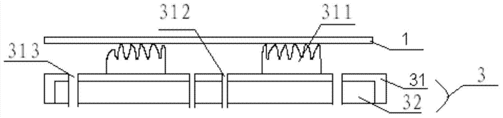
[0031] like image 3 As shown, this embodiment provides an electrode 3 for dry etching equipment, including an electrode base 32 and a protective layer 31 attached to the surface of the electrode base; Structure.

[0032] In this embodiment, by designing the traditional integral electrode as an electrode base 32 and a protective layer 31 attached to the surface of the electrode base 32, the reactants and by-products attached to the protective layer 31 after the electrode 3 has been working for a period of time will soon When the etching of the glass substrate 1 is affected, the protective layer 31 is replaced; there is no need to disassemble the lower electrode 3 for ceramic cleaning or peeling maintenance, avoiding high-intensity electrode maintenance operations.

[0033] Preferably, the electrode base includes side surfaces facing the upper surface and the periphery of the glass substrate 1 , and the above-mentioned side surfaces and upper surfaces are covered by the protec...

Embodiment 2

[0044] The present embodiment provides a method for preparing the above-mentioned electrodes, comprising the following steps:

[0045]1). The step of cleaning the surface of the electrode substrate;

[0046] Wipe the surface of the electrode substrate with a dust-free cloth dipped in alcohol or other detergent to ensure the cleanliness of the contact surface between the electrode substrate and the protective layer to prevent poor adhesion or bubbles during lamination.

[0047] 2). A step of attaching the protective layer to the surface of the electrode substrate.

[0048] In order to ensure the bonding strength, when bonding, apply an adhesive to the surface of the protective layer facing the electrode base. It should be understood that the adhesive can be easily removed by solvent or cold and heat treatment and can be selected to meet the equipment process requirements .

[0049] Alternatively, in order to improve the fluidity of the protective layer and improve the flatnes...

Embodiment 3

[0052] This embodiment provides a dry etching device, including the above-mentioned electrode, which is arranged under the substrate to be etched to support the substrate to be etched, and forms an etching electric field with the electrode arranged above the substrate to be etched.

[0053] The beneficial effects of Embodiment 2-3 are: by splitting the electrode, the electrode includes an electrode base and a protective layer attached to the upper surface and side surfaces of the electrode base; the protective layer has a structure that matches the electrode base . When the reactants and by-products attached to the protective layer will affect the etching of the glass substrate after the electrode has been working for a period of time, the protective layer can be partially replaced; there is no need to disassemble the electrode for ceramic cleaning or peeling maintenance, avoiding high strength Electrode maintenance work; at the same time, by designing the protective layer as ...


PUM


Abstract

The invention provides an electrode and a preparation method thereof and a dry etching device of the electrode. Through separate design of the electrode, the electrode includes an electrode substrate and a protection layer attached on the upper surface and side surfaces of the electrode substrate. The protection layer has a structure which matches the electrode substrate. When reactants and by-products attached on the protection layer are to affect etching of a glass substrate after the electrode works for a period of time, the protection layer can be partly replaced. Ceramic cleaning or stripping maintenance is carried out without disassembly of the electrode so that high-intensity electrode maintenance work is prevented. At the same time, the protection layer is designed into a film layer with elasticity so that friction and collision of the glass substrate and protrusions are reduced and pressure damage defect of the back part of the glass substrate is prevented.

Description

technical field [0001] The invention relates to the technical field of dry etching equipment, in particular to an electrode for dry etching equipment, a preparation method thereof, and dry etching equipment. Background technique [0002] The existing dry etching equipment is provided with an electrode below the etching chamber, and the electrode and the electrode arranged above the etching chamber form an electrode pair, and the electrode pair is pressurized to form an etching electric field, for example, the electric field can be Guide and accelerate the plasma so that it has a certain energy. When it bombards the surface of the object to be etched, the atoms of the material to be etched will be knocked out, so as to realize the etching by physical energy transfer. Purpose. [0003] In addition, an electrostatic chuck is provided under the electrode under the etching chamber, and the support and adsorption of the glass substrate (object to be etched) is realized by adjusti...

Claims


Application Information

Patent Timeline
Patent Type & Authority Applications(China)
IPC IPC(8): H01J37/32
CPCH01J37/32532H01J37/32559H01L21/3065
Inventor 陈程吕艳明
Owner HEFEI BOE OPTOELECTRONICS TECH
Why Eureka
Eureka Blog
Learn More